


The-wailing-siren
#voltage-controlled oscillator
#transistor
#feedback
#frequency range
#pushbutton switch
#capacitor
#resistor
#VCO
#siren
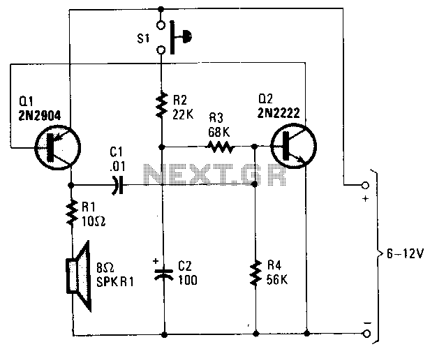
Description: Transistors Q1 and Q2, with feedback provided via C1 from the collector of Q1 to the base of Q2, form a voltage-controlled oscillator (VCO). Depending on the voltage applied to the base of Q2, the VCO frequency ranges from approximately 60 Hz to 7.5 kHz. The instantaneous voltage applied to the base of Q2 is determined by the values of C2, R2, R3, and R4. When pushbutton switch S1 is closed, C2 charges relatively quickly to the maximum supply voltage through R2, a 22 kΩ fixed resistor. This causes the siren sound to rise swiftly to its highest frequency. When the button is released, the capacitor discharges through R3 and R4, which have a combined resistance of 124 kΩ, resulting in the siren sound decaying from a high-pitched wail to a low growl. To experiment with the pitch of the sound at its highest frequency, different values for C1 can be tried. Increasing its value will produce lower notes, while decreasing it will yield higher ones. Adjusting the value of R2 will alter the attack time, with a 100 kΩ resistor providing equal attack and decay times. The manner in which the pushbutton is handled influences the overall effect.
The circuit described utilizes a pair of transistors, designated Q1 and Q2, to create a voltage-controlled oscillator (VCO). The feedback mechanism from the collector of Q1 to the base of Q2 through capacitor C1 is instrumental in establishing the oscillation frequency. The fundamental frequency range of the VCO is adjustable between 60 Hz and 7.5 kHz, contingent upon the voltage level applied to Q2’s base. This voltage is influenced by the capacitive and resistive components in the circuit, specifically capacitors C2 and C1, and resistors R2, R3, and R4.
Upon activation of the pushbutton switch S1, capacitor C2 begins to charge through the resistor R2, which is fixed at 22 kΩ. This rapid charging process results in an immediate increase in frequency, producing a siren sound that escalates quickly. The transition from a low to a high frequency is characterized by a sharp rise in pitch, creating an attention-grabbing auditory effect.
When S1 is released, the discharge path for C2 is established through resistors R3 and R4, which combine to form a resistance of 124 kΩ. This configuration allows for a gradual decay of the oscillation, where the sound transitions from a high-pitched wail to a deeper growl. The time constants associated with the charging and discharging processes are critical to the sound characteristics. The values of R2, R3, and R4 can be selected to fine-tune the attack and decay times of the sound. A resistor value of 100 kΩ for R2 is noted to provide a balance between the attack and decay phases.
Furthermore, the choice of capacitor C1 is pivotal in determining the pitch of the highest frequency produced by the VCO. Experimentation with different capacitance values for C1 allows for a variety of tonal outputs; larger capacitance values will lower the pitch, while smaller values will elevate it. This versatility in component selection provides flexibility in sound design, making it suitable for various applications requiring sound modulation. The interaction between the pushbutton switch and the circuit components creates a dynamic system where user input can significantly alter the audio output, offering a hands-on approach to sound synthesis.Transistors Ql and Q2, with feedback provided via Cl from the collector of Ql to the base of Q2, forms a voltage-controlled oscillator (VCO). De- pending on the voltage applied to Q2 "s base, the VCO frequency ranges from around 60 Hz to 7.5 kHz.
The instantaneous voltage applied to the base of Q2 is determined by the values of C2, R2, R3, and R4. When pushbutton switch Sl is closed, C2 charges fairly rapidly to the maximum supply voltage through R2, a 22-KO fixed resistor.
That causes the siren sound to rise rapidly to its highest frequency. When the button is released, the capacitor discharges through R3 and R4 with a combined resistance of 124 KO, causing the siren sound to decay from a high-pitched wail to a low growl. If you want to experiment with the pitch of the sound at its highest frequency, try different values for Cl.
Increase its value for lower notes, and decrease it for higher ones. Different values for R2 will change the attack time. A 100-KO resistor provides equal attack and decay times. The way you handle the pushbutton varies the effect.
The circuit described utilizes a pair of transistors, designated Q1 and Q2, to create a voltage-controlled oscillator (VCO). The feedback mechanism from the collector of Q1 to the base of Q2 through capacitor C1 is instrumental in establishing the oscillation frequency. The fundamental frequency range of the VCO is adjustable between 60 Hz and 7.5 kHz, contingent upon the voltage level applied to Q2’s base. This voltage is influenced by the capacitive and resistive components in the circuit, specifically capacitors C2 and C1, and resistors R2, R3, and R4.
Upon activation of the pushbutton switch S1, capacitor C2 begins to charge through the resistor R2, which is fixed at 22 kΩ. This rapid charging process results in an immediate increase in frequency, producing a siren sound that escalates quickly. The transition from a low to a high frequency is characterized by a sharp rise in pitch, creating an attention-grabbing auditory effect.
When S1 is released, the discharge path for C2 is established through resistors R3 and R4, which combine to form a resistance of 124 kΩ. This configuration allows for a gradual decay of the oscillation, where the sound transitions from a high-pitched wail to a deeper growl. The time constants associated with the charging and discharging processes are critical to the sound characteristics. The values of R2, R3, and R4 can be selected to fine-tune the attack and decay times of the sound. A resistor value of 100 kΩ for R2 is noted to provide a balance between the attack and decay phases.
Furthermore, the choice of capacitor C1 is pivotal in determining the pitch of the highest frequency produced by the VCO. Experimentation with different capacitance values for C1 allows for a variety of tonal outputs; larger capacitance values will lower the pitch, while smaller values will elevate it. This versatility in component selection provides flexibility in sound design, making it suitable for various applications requiring sound modulation. The interaction between the pushbutton switch and the circuit components creates a dynamic system where user input can significantly alter the audio output, offering a hands-on approach to sound synthesis.Transistors Ql and Q2, with feedback provided via Cl from the collector of Ql to the base of Q2, forms a voltage-controlled oscillator (VCO). De- pending on the voltage applied to Q2 "s base, the VCO frequency ranges from around 60 Hz to 7.5 kHz.
The instantaneous voltage applied to the base of Q2 is determined by the values of C2, R2, R3, and R4. When pushbutton switch Sl is closed, C2 charges fairly rapidly to the maximum supply voltage through R2, a 22-KO fixed resistor.
That causes the siren sound to rise rapidly to its highest frequency. When the button is released, the capacitor discharges through R3 and R4 with a combined resistance of 124 KO, causing the siren sound to decay from a high-pitched wail to a low growl. If you want to experiment with the pitch of the sound at its highest frequency, try different values for Cl.
Increase its value for lower notes, and decrease it for higher ones. Different values for R2 will change the attack time. A 100-KO resistor provides equal attack and decay times. The way you handle the pushbutton varies the effect.
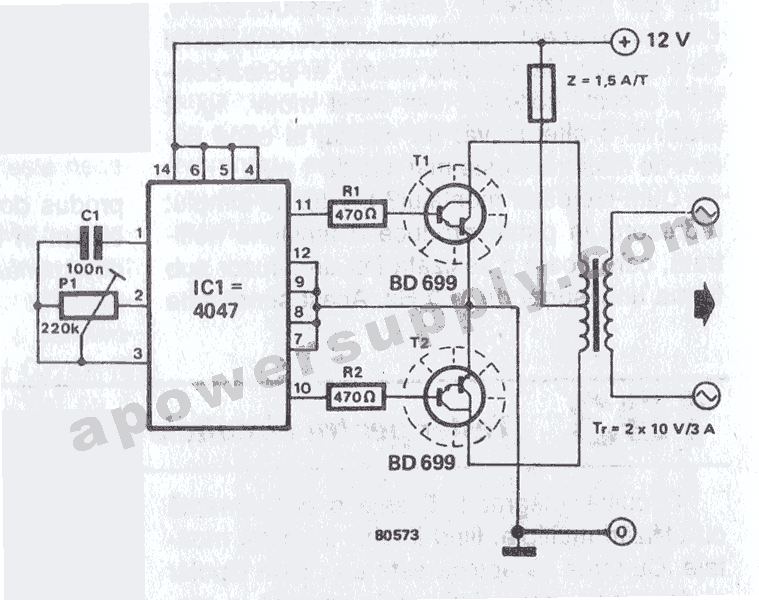
Transistor inverter circuit 6
This is a transistor inverter circuit diagram rated for 100 watts, designed as an easy-to-build circuit. It utilizes only transistors and does not incorporate any integrated circuits. The circuit converts a 12V battery input to a 220V, 50Hz square wave...
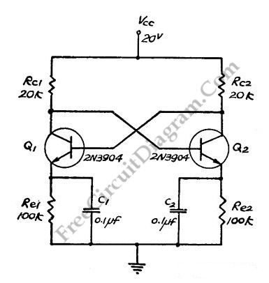
Direct Coupled Discrete Astable Multivibrator circuit
This flip-flop circuit functions as a free-running astable multivibrator, where the bases and collectors of both emitter-biased transistors are directly coupled. The switching action is facilitated by a capacitor in each emitter circuit, resulting in the generation of triangle waves...
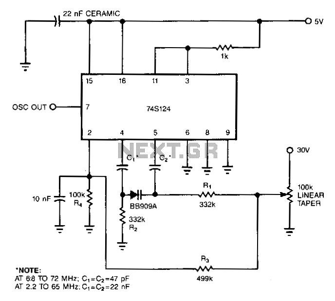
Variable-capacitance-diode-sparked-vco
A 7415124 multivibrator can be converted into a wideband voltage-controlled oscillator (VCO) by substituting the conventional fixed capacitor with a variable-capacitance diode. The primary drawback of this configuration is the 30-V biasing voltage required by the diode. Capacitors C1 and...
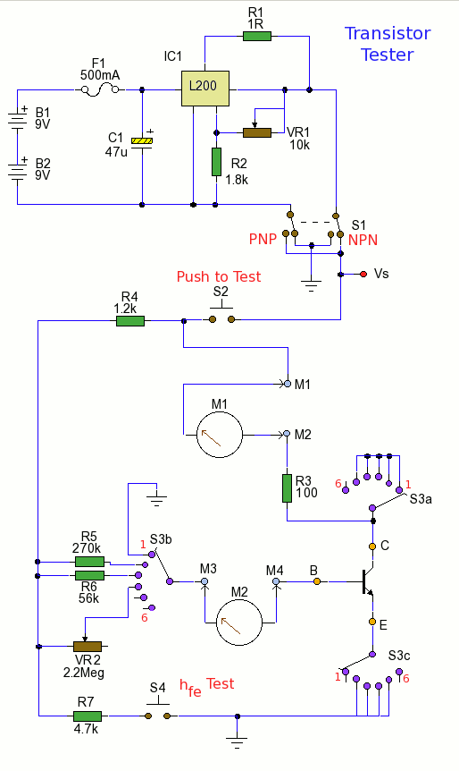
Transistor Tester
This circuit can measure both small signal hfe and DC current gain hFE of a low to medium power transistor.
The circuit is designed to evaluate the current gain characteristics of low to medium power transistors by measuring both the small...
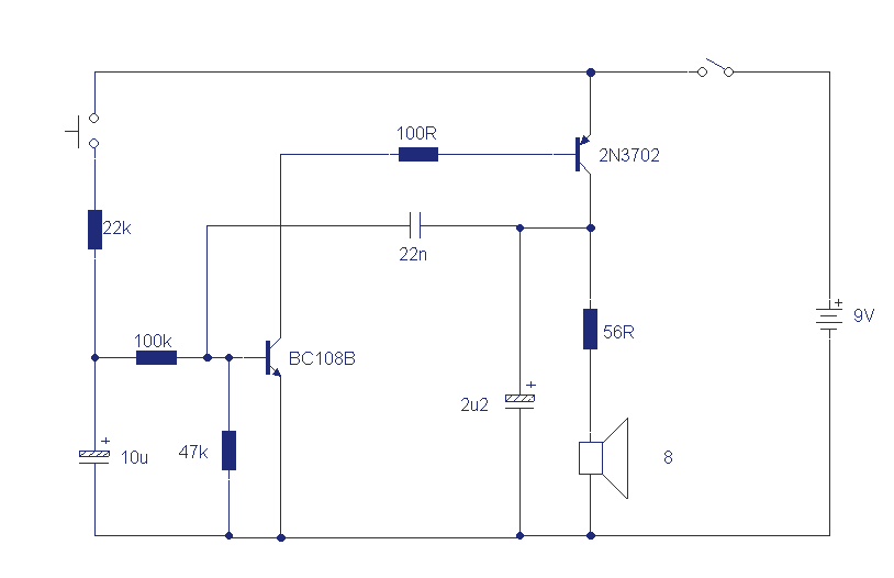
Siren
An electronic siren made from discrete components. The sound produced imitates the rise and fall of an American police siren. When first switched on the 10u capacitors is discharged and both transistors are off. When the push button switch is...
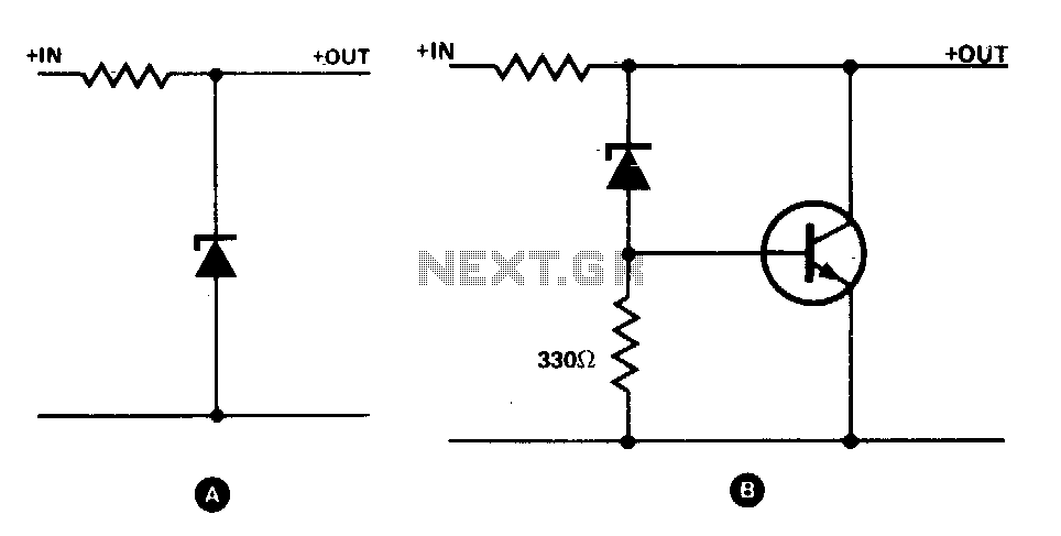
Transistor increases zener rating
The simple zener shunt in configuration A may not handle sufficient current if the zener diode available is of low wattage. A power transistor will perform most of the work for the zener as illustrated in configuration B. Once the...

Transistor Amplifier Circuit with Diagram for 12 Watts
A simple transistor amplifier circuit diagram and schematic that can be used as a 12-watt audio transistor amplifier. An operational amplifier (op-amp) integrated circuit (IC) is used to produce the required gain.
This circuit is designed to amplify audio signals, making...
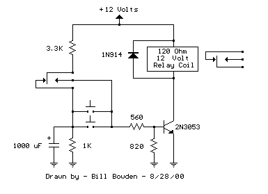
1 Transistor Toggle Relay schematic
The circuit below requires a double pole, double throw relay in conjunction with a single transistor to allow toggling the relay with a momentary push button. One set of relay contacts is used to control the load, while the other...
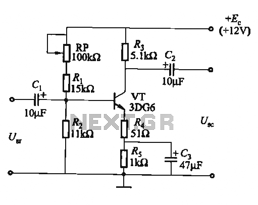
Transistor common emitter amplifier circuit
The circuit is a bias circuit for automatic stabilizers that maintains a stable quiescent operating point with good thermal stability. It utilizes a three-pole tube with an NPN type transistor, characterized by a small Iceo. An adjustment potentiometer, RP, is...