


Tone Generator with 555
#555 timer
#tone generator
#frequency control
#piezoelectric
#ultrasonic transducer
#robot control
#capacitor
#audio frequency
#signal generation
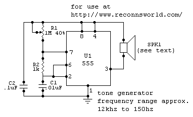
Description: this tone generator can be used to control your robot. you will need to use the tone decoder for this. to widen the range, higher or lower - substitute a higher, or lower valued capacitor for c1. for frequencies about 5khz and 15khz, use a piezoelectric element as the speaker. Use a miniature speaker for frequencies under 5khz, and use an ultrasonic transducer for frequencies over 30khz. More: all resistors are 5 or 10 percent tolerance, 1/4-watt all capacitors are 10 percent tolerance, rated 35 volts or higher.
The tone generator circuit is designed to produce audio signals that can be utilized for controlling robotic systems. The operation of this circuit relies on a tone decoder, which interprets the generated tones and translates them into commands for the robot.
To achieve a desired frequency range, the circuit incorporates a variable capacitor, designated as C1. By substituting C1 with a capacitor of different capacitance value, the frequency output can be adjusted to either higher or lower ranges. For generating tones within the range of approximately 5 kHz to 15 kHz, a piezoelectric element is recommended as the output speaker. This component is effective for producing clear tones in this frequency range.
For lower frequencies, specifically those below 5 kHz, a miniature speaker is preferred, as it is better suited for producing sound in this range without distortion. Conversely, for applications requiring frequencies above 30 kHz, an ultrasonic transducer should be utilized. This type of transducer is capable of generating sound waves beyond the audible range, which can be beneficial for certain robotic applications, such as ultrasonic sensing.
The circuit components are selected with specific tolerances to ensure reliability and performance. All resistors used in the circuit are rated at either 5% or 10% tolerance and are capable of handling a power rating of 1/4 watt. Additionally, all capacitors have a tolerance of 10% and are rated for voltages of 35 volts or higher to ensure safe operation within the circuit. Proper selection and arrangement of these components are crucial for the effective functioning of the tone generator.this tone generator can be used to control your robot. you will need to use the tone decoder for this. to widen the range, higher or lower - substitute a higher, or lower valued capacitor for c1. for frequencies about 5khz and 15khz, use a piezoelectric element as the speaker. Use a miniature speaker for frequencies under 5khz, and use an ultrasonic transducer for frequencies over 30khz. all resistors are 5 or 10 percent tolerance, 1/4-watt all capacitors are 10 percent tolerance, rated 35 volts or higher
The tone generator circuit is designed to produce audio signals that can be utilized for controlling robotic systems. The operation of this circuit relies on a tone decoder, which interprets the generated tones and translates them into commands for the robot.
To achieve a desired frequency range, the circuit incorporates a variable capacitor, designated as C1. By substituting C1 with a capacitor of different capacitance value, the frequency output can be adjusted to either higher or lower ranges. For generating tones within the range of approximately 5 kHz to 15 kHz, a piezoelectric element is recommended as the output speaker. This component is effective for producing clear tones in this frequency range.
For lower frequencies, specifically those below 5 kHz, a miniature speaker is preferred, as it is better suited for producing sound in this range without distortion. Conversely, for applications requiring frequencies above 30 kHz, an ultrasonic transducer should be utilized. This type of transducer is capable of generating sound waves beyond the audible range, which can be beneficial for certain robotic applications, such as ultrasonic sensing.
The circuit components are selected with specific tolerances to ensure reliability and performance. All resistors used in the circuit are rated at either 5% or 10% tolerance and are capable of handling a power rating of 1/4 watt. Additionally, all capacitors have a tolerance of 10% and are rated for voltages of 35 volts or higher to ensure safe operation within the circuit. Proper selection and arrangement of these components are crucial for the effective functioning of the tone generator.this tone generator can be used to control your robot. you will need to use the tone decoder for this. to widen the range, higher or lower - substitute a higher, or lower valued capacitor for c1. for frequencies about 5khz and 15khz, use a piezoelectric element as the speaker. Use a miniature speaker for frequencies under 5khz, and use an ultrasonic transducer for frequencies over 30khz. all resistors are 5 or 10 percent tolerance, 1/4-watt all capacitors are 10 percent tolerance, rated 35 volts or higher
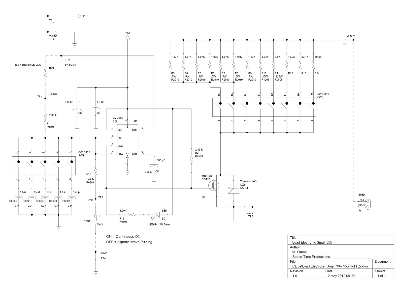
load electronic small 555
This is a license to use the files to manufacture up to 12 boards. If additional boards are required, please make contact. It is important to note that the order must specify the intent to produce 12 or fewer boards....
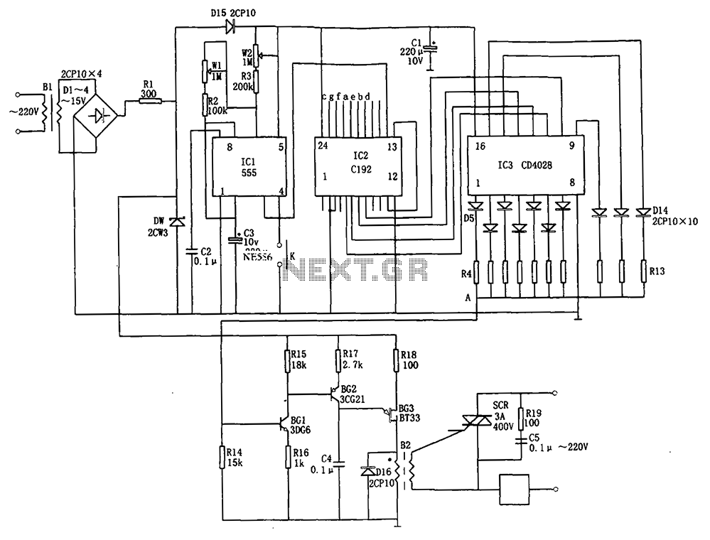
Automatic conversion l0 wind speed controller C192 555 CD4028
The automatic conversion circuit for wind speed control is depicted in Figure 10. This circuit consists of a clock signal generator (IC1), a counter (IC2), a decoder (IC3), a synchronous phase shifting circuit (BG1, BG2, BG3), a thyristor control circuit...
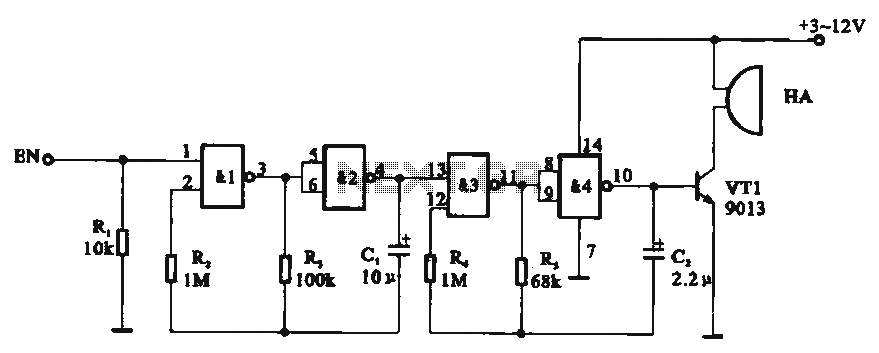
Tone generator circuit
Tone generator circuit. The tone generator circuit utilizes a quad 2-input NAND gate integrated circuit, specifically the CD4011. NAND gates 1 and 2, along with NAND gates 3 and 4, form two gating multivibrator oscillators. The oscillation period of the...
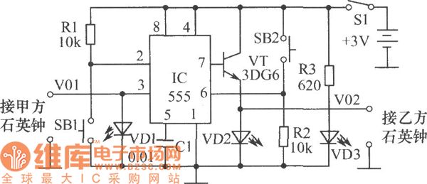
The clock circuit diagram for racing
The chart illustrates a clock designed for a competition, utilizing a 555 timer circuit. This circuit is characterized by its novel design, reliable performance, ease of assembly, and engaging functionality. The 555 timer is available in two types: bipolar (TTL)...
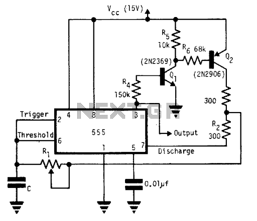
Square-wave generator with 555
A single timing resistor ensures that the output is a square (50% duty cycle) wave at all frequency settings. Any 555 type of chip will do the job.
The circuit utilizes a 555 timer IC configured in astable mode to generate...
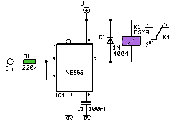
Voltage Controlled Switch using 555 Timer
In this circuit, the 555 timer is utilized in an innovative manner as a voltage-controlled switch. The widely used NE555 can perform effectively in various applications.
The 555 timer, a versatile integrated circuit, is commonly employed in timer, delay, pulse generation,...
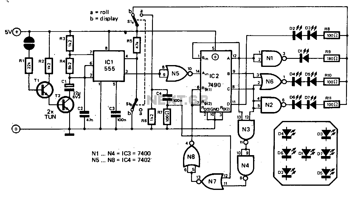
Electronic-dice
The basic die circuit is provided. A 555 timer, IC1, is configured as an astable multivibrator that generates clock pulses. These pulses are sent to a divide-by-six counter, IC2, whose outputs are decoded by gates N1 to N6 to illuminate...
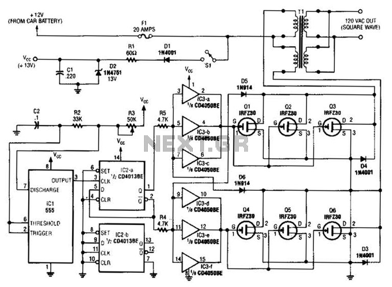
250W Inverter Circuit
A 555 timer (IC1) generates a 120-Hz signal that is fed to a CD4013BE flip-flop (IC1-a), which divides the input frequency by two to generate a 60-Hz clocking frequency for the FET array (Q1 through Q6). Transformer T1 is a...
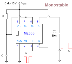
555 timer ic operation
The 555 Timer is an integrated circuit utilized for various functions such as timing, pulse generation, and tone generation, all from a single universal IC. Each pin's function is detailed, and design recommendations are provided as necessary. A Monostable Multivibrator...