


Triangle-to-sine converters
#triangle wave
#sine wave
#waveform conversion
#diode-resistor shaping
#P-channel junction FET
#distortion
#566
#signal processing
#non-linear transfer
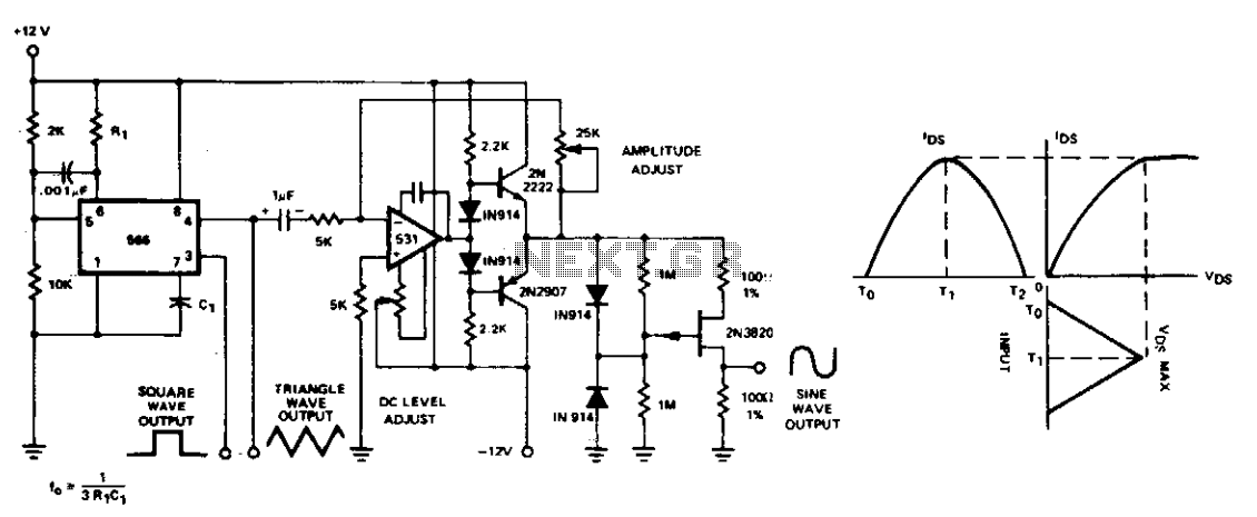
Description: The conversion of triangle waveforms to sinusoidal waveforms is typically achieved using diode-resistor shaping networks, which effectively reconstruct the sine wave segment by segment. Two simpler and more cost-effective methods can be employed to shape the triangle waveform of the 566 into a sinusoid with less than 2% distortion. A non-linear IDSVDS transfer characteristic of a P-channel junction FET is utilized for this waveform shaping.
The amplitude of the triangle waveform is critical and must be meticulously adjusted to obtain a low distortion sinusoidal output. When greater waveform accuracy is required, the diode-resistor shaping technique can be applied to the 566, yielding excellent results due to its high output amplitude stability when powered by a regulated supply.
The conversion process begins with the generation of a triangle waveform, which is characterized by its linear rise and fall times. This waveform is then fed into a shaping circuit, which can include a P-channel junction FET. The non-linear characteristics of the FET facilitate the transformation of the linear triangle waveform into a more sinusoidal shape by exploiting its IDSVDS transfer function.
In practical applications, the triangle waveform amplitude should be set within a specific range to minimize distortion in the resultant sinusoidal output. This involves precise adjustments to the input signal before it enters the shaping circuit. For applications requiring high fidelity, the diode-resistor shaping network provides an alternative solution. This network allows for fine-tuning of the waveform characteristics and can significantly enhance the accuracy of the output signal.
The diode-resistor network operates by selectively clipping and smoothing the triangle waveform, effectively converting its sharp edges into the smoother transitions characteristic of a sine wave. The stability of the output amplitude when using a regulated power supply is crucial, as fluctuations in supply voltage can lead to variations in the output waveform, potentially introducing distortion. Thus, ensuring a stable operating environment is essential for achieving high-quality sinusoidal outputs from triangle waveforms.Conversion of triangle wave shapes to sinusoids is usually accomplished by diode-resistor shaping networks, which accurately reconstruct the sine wave segment by segment. Two simpler and less costly methods may be used to shape the triangle waveform of the 566 into a sinusoid with less than 2% distortion.
The non-linear IDSVDS transfer characteristic of a P-channel junction FET is used to shape the triangle waveform. The amplitude of the triangle waveform is critical and must be carefully adjusted to achieve a low distortion sinusoidal output. Naturally, where additional waveform accuracy is needed, the diode-resistor shaping scheme can be applied to the 566 with excellent results since it has very good output amplitude stability when operated from a regulated supply.
The amplitude of the triangle waveform is critical and must be meticulously adjusted to obtain a low distortion sinusoidal output. When greater waveform accuracy is required, the diode-resistor shaping technique can be applied to the 566, yielding excellent results due to its high output amplitude stability when powered by a regulated supply.
The conversion process begins with the generation of a triangle waveform, which is characterized by its linear rise and fall times. This waveform is then fed into a shaping circuit, which can include a P-channel junction FET. The non-linear characteristics of the FET facilitate the transformation of the linear triangle waveform into a more sinusoidal shape by exploiting its IDSVDS transfer function.
In practical applications, the triangle waveform amplitude should be set within a specific range to minimize distortion in the resultant sinusoidal output. This involves precise adjustments to the input signal before it enters the shaping circuit. For applications requiring high fidelity, the diode-resistor shaping network provides an alternative solution. This network allows for fine-tuning of the waveform characteristics and can significantly enhance the accuracy of the output signal.
The diode-resistor network operates by selectively clipping and smoothing the triangle waveform, effectively converting its sharp edges into the smoother transitions characteristic of a sine wave. The stability of the output amplitude when using a regulated power supply is crucial, as fluctuations in supply voltage can lead to variations in the output waveform, potentially introducing distortion. Thus, ensuring a stable operating environment is essential for achieving high-quality sinusoidal outputs from triangle waveforms.Conversion of triangle wave shapes to sinusoids is usually accomplished by diode-resistor shaping networks, which accurately reconstruct the sine wave segment by segment. Two simpler and less costly methods may be used to shape the triangle waveform of the 566 into a sinusoid with less than 2% distortion.
The non-linear IDSVDS transfer characteristic of a P-channel junction FET is used to shape the triangle waveform. The amplitude of the triangle waveform is critical and must be carefully adjusted to achieve a low distortion sinusoidal output. Naturally, where additional waveform accuracy is needed, the diode-resistor shaping scheme can be applied to the 566 with excellent results since it has very good output amplitude stability when operated from a regulated supply.

Sine wave converter circuit
The circuit serves as a signal source for calibration level meters or sensor-driven differential transformers. The oscillation frequency is determined by the 74HC04, producing a frequency of 1 kHz through resistor R. The supply voltage of the circuit changes in...
Fuzz Face
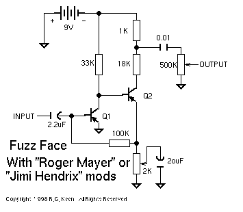
This is simple almost beyond belief for distortion devices. Two transistors, four resistors, three capacitors, and two controls make all that tone. The first transistor is set up with the simplest of arrangements - input through a DC blocking capacitor...
Triangle wave generator circuit with cmos inverter IC
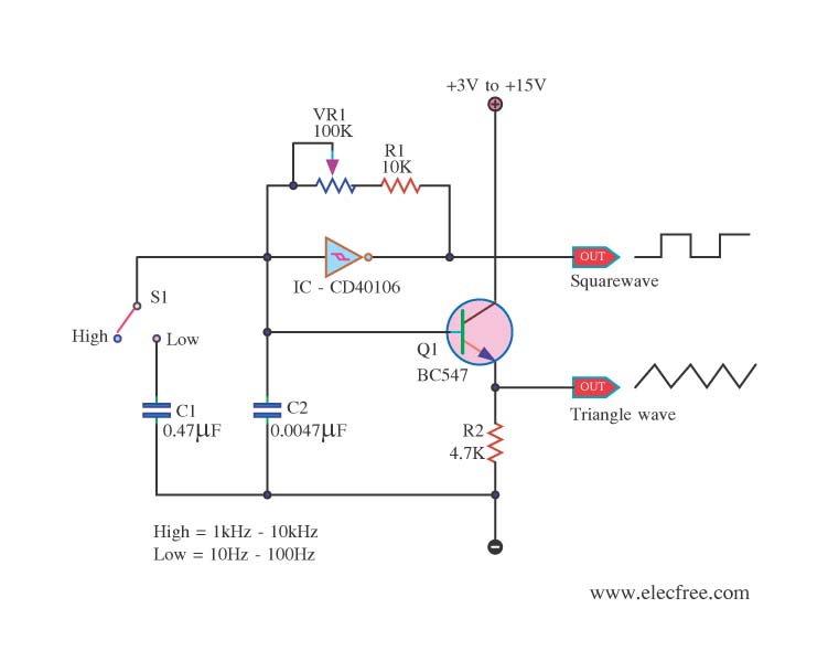
This is a function generator project that can be used as a triangle and square wave generator. The main components include the CD40106, a popular CMOS integrated circuit, and a standard transistor.
The function generator circuit utilizes the CD40106, which is...
Triangle-generator
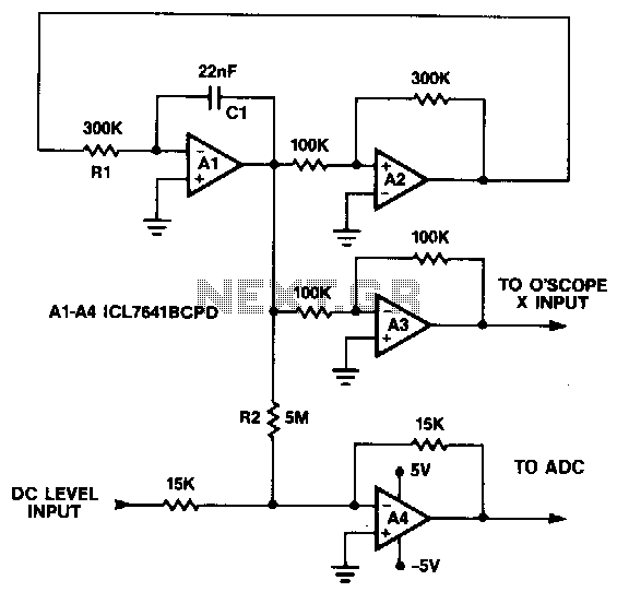
This circuit generates a symmetrical 10 mV peak-to-peak triangle waveform that is summed with a DC level and connected to the analog input for noise and DNL testing. The DC level input offsets the triangle waveform over the input range...
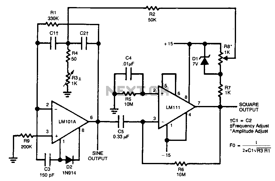
Sine-square-wave-oscillator
The circuit is designed to generate both sine and square wave outputs for frequencies ranging from below 20 Hz to above 20 kHz. The frequency of oscillation can be easily adjusted by modifying a single resistor, which is a significant...
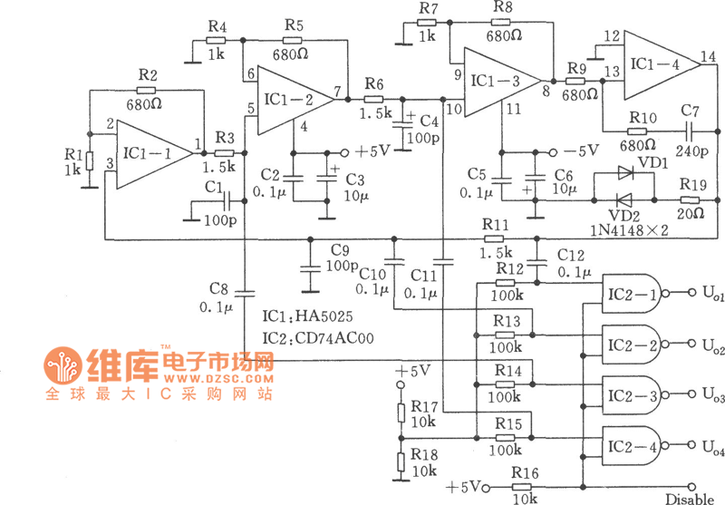
High-performance quadrature sine wave type oscillator circuit
Many RC oscillators utilize advanced circuits within the phase shift unit. These circuits employ voltage feedback amplifiers, whose gain decreases significantly at high frequencies and ceases when high frequency is not attained. The variation in the phase characteristics of the...
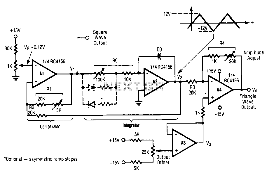
Triangle-square-wave-generator
This circuit utilizes a positive-feedback loop that encompasses a combined comparator and integrator. Upon the application of power, the output of the comparator transitions to one of two states, either the maximum positive or maximum negative voltage. This action delivers...
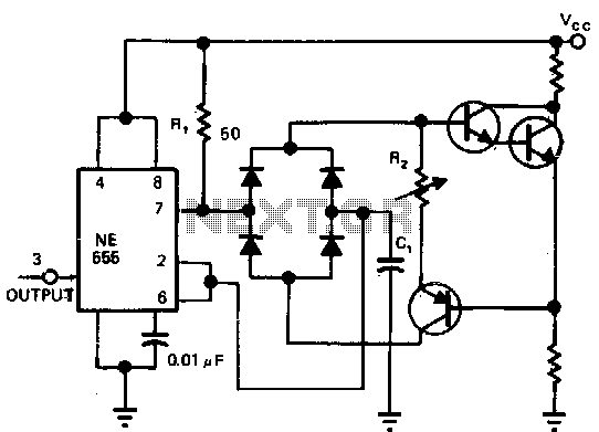
Linear-triangle-wave-timer
Utilizing a single current source for both the charge and discharge paths in this circuit guarantees that the rise and fall times at the capacitor terminal are identical. A Darlington pair is employed to ensure consistent biasing of the integrated...
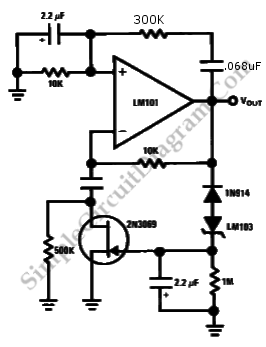
Wien Bridge Sine Wave Oscillator
Achieving the appropriate amplifier loop gain is a significant challenge in generating a low distortion, constant amplitude sine wave. Nevertheless, this issue can be addressed with...
Amplifier loop gain is a critical parameter in the design of audio and signal processing...