


ujt triggering circuit
#UJT
#triggering
#semiconductor
#pulse generator
#relaxation oscillator
#electronics
#circuit design
#transistor
#waveform generation
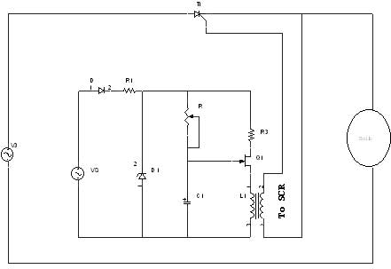
Description: A unijunction transistor (UJT) is an electronic semiconductor device characterized by a single junction. It consists of three terminals: an emitter (E) and two bases (B1 and B2). The base is constructed from a lightly doped n-type silicon bar, with two ohmic contacts (B1 and B2) connected at each end. The emitter is p-type and heavily doped. The resistance between B1 and B2, when the emitter is in an open-circuit state, is referred to as interbase resistance. Initially, a capacitor charges through a resistor (R), with the voltage applied to the emitter of the UJT. When the voltage across the capacitor reaches the peak point voltage of the UJT, the device switches to an "on" state. Consequently, the capacitor discharges through the output resistance, generating a pulse in the circuit.
A unijunction transistor (UJT) operates primarily as a switching device and is widely used in pulse generation and timing applications. The unique structure of the UJT allows it to exhibit negative resistance characteristics, which are essential for its functionality in oscillator circuits. The emitter, being heavily doped, creates a significant potential barrier at the junction with the n-type material of the base.
In typical applications, the UJT is employed in relaxation oscillators where the charging and discharging of the capacitor through the resistor determines the frequency of the output pulse. The charging time is influenced by the value of the resistor (R) and the capacitance (C), while the discharging process occurs rapidly once the UJT is turned on.
The interbase resistance plays a crucial role in the operation of the UJT, as it affects the voltage levels at which the device switches states. The peak point voltage (V_P) is a critical parameter; it is the voltage at which the UJT transitions from its off state to its on state, allowing for the rapid discharge of the capacitor.
In a practical circuit, the UJT may be connected to additional components such as diodes or transistors to shape the output waveform or to enhance the triggering mechanism. The output pulse generated can be utilized to drive other circuits, providing a simple yet effective means of generating timed signals. The versatility of the UJT makes it an essential component in various electronic applications, including timing circuits, pulse generators, and even in some types of oscillators.A unijunction transistor (UJT) is an electronic semiconductor device that has only one junction. The UJT has three terminals: an emitter (E) and two bases (B1 and B2). The base is formed by lightly doped n-type bar of silicon. Two ohmic contacts B1 and B2 are attached at its ends. The emitter is of p-type and it is heavily doped. The resistance be tween B1 and B2, when the emitter is open-circuit is called interbase resistance. Initially the capacitor charges through R whose voltage is applied to the emitter of UJT. When the capacitor voltage reaches peak point voltage of UJT. the UJT will switch to on condition. Now the capacitor discharges through the output resistance. Thus the pulse is generated in the circuit.
A unijunction transistor (UJT) operates primarily as a switching device and is widely used in pulse generation and timing applications. The unique structure of the UJT allows it to exhibit negative resistance characteristics, which are essential for its functionality in oscillator circuits. The emitter, being heavily doped, creates a significant potential barrier at the junction with the n-type material of the base.
In typical applications, the UJT is employed in relaxation oscillators where the charging and discharging of the capacitor through the resistor determines the frequency of the output pulse. The charging time is influenced by the value of the resistor (R) and the capacitance (C), while the discharging process occurs rapidly once the UJT is turned on.
The interbase resistance plays a crucial role in the operation of the UJT, as it affects the voltage levels at which the device switches states. The peak point voltage (V_P) is a critical parameter; it is the voltage at which the UJT transitions from its off state to its on state, allowing for the rapid discharge of the capacitor.
In a practical circuit, the UJT may be connected to additional components such as diodes or transistors to shape the output waveform or to enhance the triggering mechanism. The output pulse generated can be utilized to drive other circuits, providing a simple yet effective means of generating timed signals. The versatility of the UJT makes it an essential component in various electronic applications, including timing circuits, pulse generators, and even in some types of oscillators.A unijunction transistor (UJT) is an electronic semiconductor device that has only one junction. The UJT has three terminals: an emitter (E) and two bases (B1 and B2). The base is formed by lightly doped n-type bar of silicon. Two ohmic contacts B1 and B2 are attached at its ends. The emitter is of p-type and it is heavily doped. The resistance be tween B1 and B2, when the emitter is open-circuit is called interbase resistance. Initially the capacitor charges through R whose voltage is applied to the emitter of UJT. When the capacitor voltage reaches peak point voltage of UJT. the UJT will switch to on condition. Now the capacitor discharges through the output resistance. Thus the pulse is generated in the circuit.
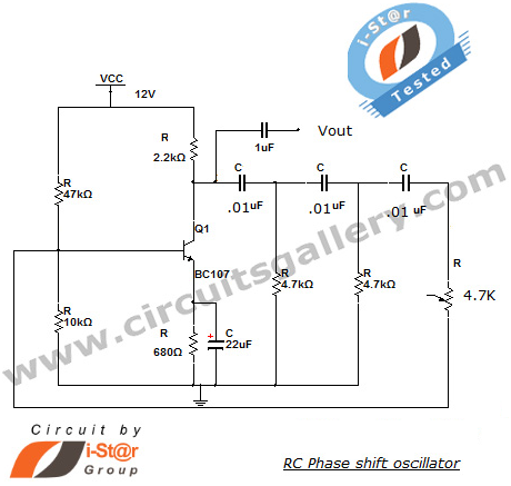
RC Phase Shift Oscillator Using Transistor (BJT): Circuit & Working
This section introduces a transistor oscillator circuit known as the RC Phase Shift Oscillator. An oscillator is an electronic circuit that functions as a sine wave generator, requiring only a DC power supply. It is commonly used in variable frequency...
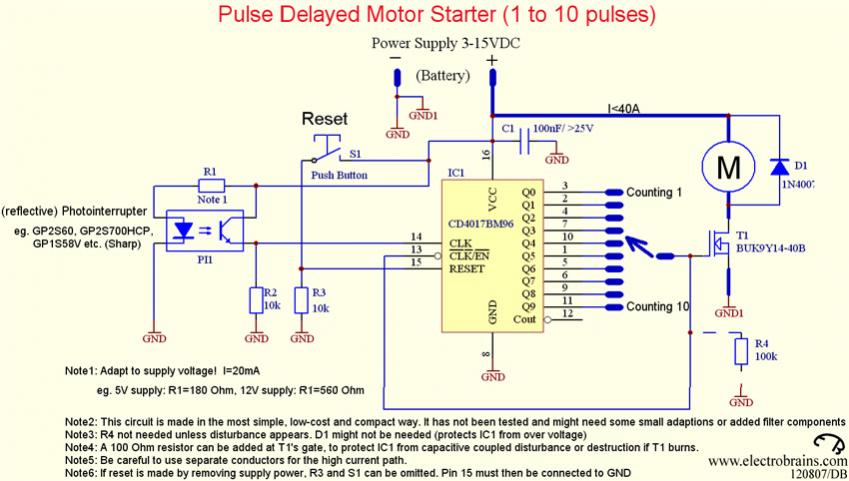
transistor circuit for counting wheel rotations
A new user has joined the forum and is seeking assistance with circuit design. They express a desire for guidance and acknowledge their inexperience in the subject.
In circuit design, it is crucial to understand the fundamental components and their interactions....
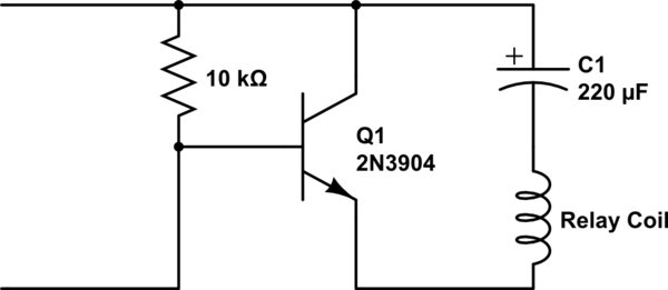
transistors Mystery circuit: latching relay control with transitor / capacitor why doesnt it work
A single-coil latching relay is utilized, which can latch and reset with opposite polarities. Testing of the circuit with dual opposite-biased LEDs showed no flickering in either direction, indicating stable charge and discharge behavior. However, there are concerns regarding the...
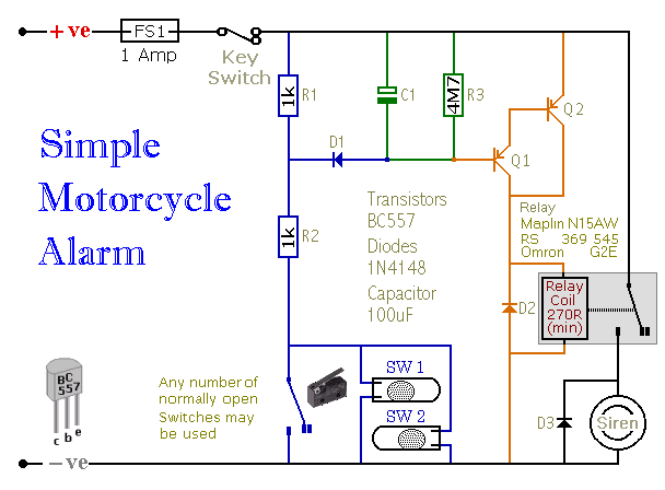
Simple Two-Transistor Motorcycle Alarm
When one of the switches is closed, the base of Q1 is connected to ground through D1 and R2. This activates Q1, which in turn activates Q2. Q2 connects the positive side of the relay coil to the supply line,...
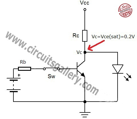
Transistor act as a switch
A transistor is a semiconductor device utilized for switching and amplifying weak signals. This article details the operation of a transistor and its function as a switch. Currently, transistors are integrated into most electronic equipment for switching applications, with digital...
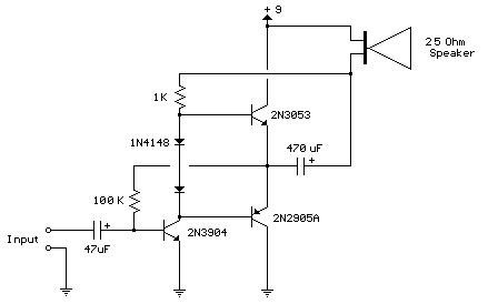
80 milliwatt Improved 3 Transistor Audio Amp
This circuit is similar to the previous one but utilizes positive feedback to increase the amplitude to the speaker. It was adapted from a small 5-transistor radio that employs a 25-ohm speaker. In the prior circuit, the load resistor for...
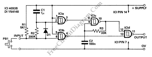
Pulse Delay Generator
This circuit is a delayed pulse generator that provides pulse rate and independent control of the initial delay. The pulse generator of this circuit is.
The delayed pulse generator circuit is designed to produce a pulse output after a specified delay,...
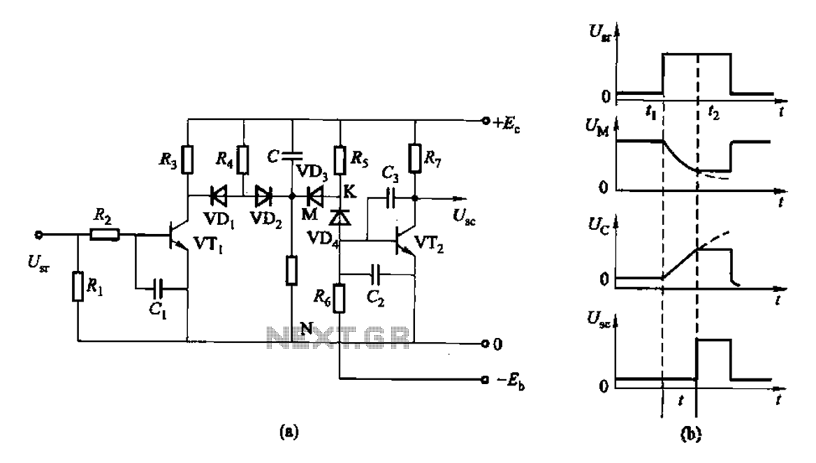
As of control rechargeable delay circuit
This is a control rechargeable delay circuit. Under normal circumstances, when there is no input signal, the transistor VTi is off. VTz is conducting, resulting in a low output potential (U). When a signal is applied, VTi turns on, VTz...
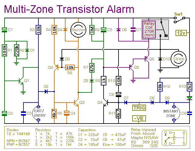
expandable transistor based burglar alarm
This transistor-based alarm system incorporates automatic exit and entry delays, along with a timed bell cut-off and system reset functionality. In addition to the exit/entry zone, the fundamental alarm board includes one instant zone, which is sufficient for many applications....