


Ultrasonic drilling machine circuit diagram 2
#ultrasonic
#drilling machine
#power supply
#preamplifier
#power amplifier
#transistor
#resistors
#capacitors
#inductor
#oscillator circuit
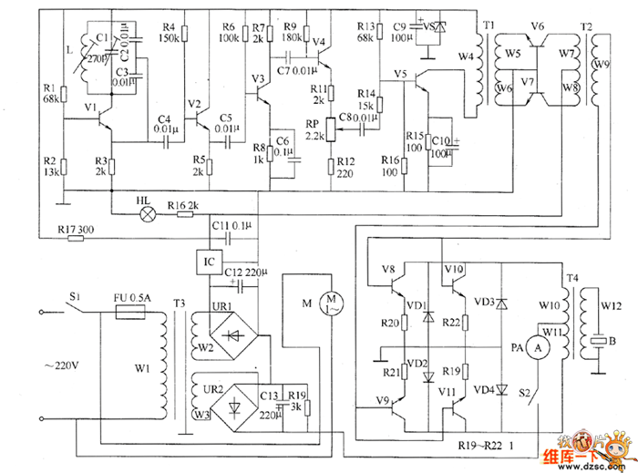
Description: The ultrasonic drilling machine circuit consists of a power supply circuit, an ultrasonic oscillator circuit, a preamplifier, a promoting amplifier circuit, and a power amplifier output circuit, as depicted in the accompanying diagram. The ultrasonic oscillator circuit is made up of resistors R1 to R4, transistor V1, capacitors C1 to C4, and an inductor L. The preamplifier circuit includes...
The ultrasonic drilling machine operates by utilizing high-frequency sound waves to facilitate drilling processes. The power supply circuit provides the necessary voltage and current to the entire system, ensuring stable operation. This circuit typically includes voltage regulators and filtering components to maintain a consistent output.
The ultrasonic oscillator circuit is the heart of the system, generating the high-frequency signals required for ultrasonic drilling. It employs a combination of resistors (R1 to R4), which determine the frequency and amplitude of the oscillations, and a transistor (V1) that acts as a switch to control the flow of current. Capacitors (C1 to C4) are used for tuning and stability, while the inductor (L) helps in shaping the oscillation waveform.
Following the oscillator, the preamplifier circuit boosts the weak signals produced by the ultrasonic oscillator. This stage is critical for ensuring that the signals are strong enough for further amplification. The promoting amplifier circuit then takes these signals and amplifies them further, preparing them for the final power amplification stage.
The power amplifier output circuit is responsible for driving the ultrasonic transducer, which converts electrical signals into mechanical vibrations. This stage must be designed to handle high power levels while maintaining efficiency and stability. Overall, each component in the ultrasonic drilling machine circuit plays a vital role in ensuring the effective generation and application of ultrasonic energy for drilling applications.The ultrasonic drilling machine circuit is composed of power supply circuit, ultrasonic oscillator circuit, preamplifier, promoting amplifier circuit and power amplifier output circuit, and the circuit is shown as the chart. Ultrasonic oscillator circuit consists of resistors R1 ~ R4, transistor V1, capacitors C1 ~ C4 and inductor L.
Preamplifier circuit con..
The ultrasonic drilling machine operates by utilizing high-frequency sound waves to facilitate drilling processes. The power supply circuit provides the necessary voltage and current to the entire system, ensuring stable operation. This circuit typically includes voltage regulators and filtering components to maintain a consistent output.
The ultrasonic oscillator circuit is the heart of the system, generating the high-frequency signals required for ultrasonic drilling. It employs a combination of resistors (R1 to R4), which determine the frequency and amplitude of the oscillations, and a transistor (V1) that acts as a switch to control the flow of current. Capacitors (C1 to C4) are used for tuning and stability, while the inductor (L) helps in shaping the oscillation waveform.
Following the oscillator, the preamplifier circuit boosts the weak signals produced by the ultrasonic oscillator. This stage is critical for ensuring that the signals are strong enough for further amplification. The promoting amplifier circuit then takes these signals and amplifies them further, preparing them for the final power amplification stage.
The power amplifier output circuit is responsible for driving the ultrasonic transducer, which converts electrical signals into mechanical vibrations. This stage must be designed to handle high power levels while maintaining efficiency and stability. Overall, each component in the ultrasonic drilling machine circuit plays a vital role in ensuring the effective generation and application of ultrasonic energy for drilling applications.The ultrasonic drilling machine circuit is composed of power supply circuit, ultrasonic oscillator circuit, preamplifier, promoting amplifier circuit and power amplifier output circuit, and the circuit is shown as the chart. Ultrasonic oscillator circuit consists of resistors R1 ~ R4, transistor V1, capacitors C1 ~ C4 and inductor L.
Preamplifier circuit con..
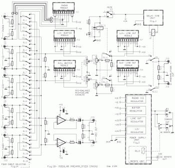
High-End Audio Modular Preamplifier
This circuit is not easy to build, but it provides excellent audio quality. It serves as a high-quality preamplifier, capable of driving high-quality power amplifiers while delivering good sound.
The described circuit functions as a high-fidelity audio preamplifier, designed to enhance...
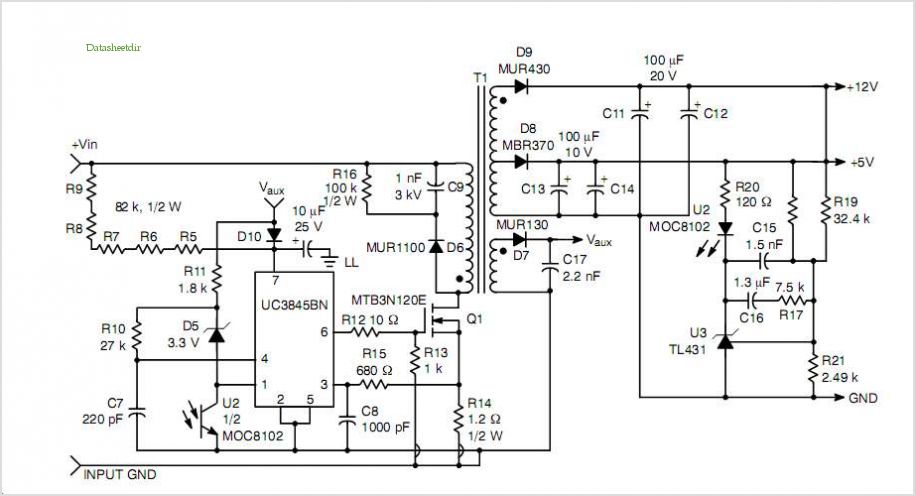
switching power supply schematic
This post summarizes the work of experts in switching power supply schematic diagrams who are thoroughly knowledgeable about all aspects of the subject.
Switching power supplies are crucial components in modern electronic devices, providing efficient voltage regulation and power conversion. The...
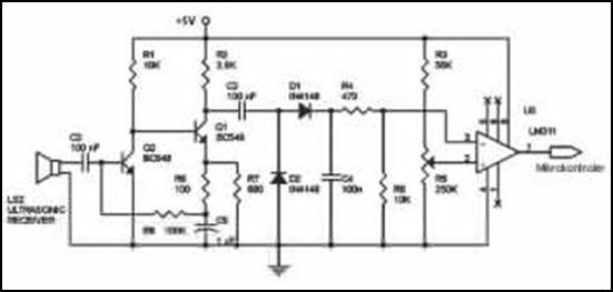
Ultrasonic Wave Receiver Circuit Schematic Diagram
Ultrasonic receivers detect an ultrasonic signal emitted by an ultrasonic transmitter at a specific frequency. The received signal is filtered using a band-pass filter circuit that allows only the predetermined frequency range to pass. The output signal is then amplified...
A Sensitive DIY Ultrasonic Range Sensor
Some ultrasonic range finders for a project. Most commercial sensors like Parallax's PING sensor and similar products are quite expensive, especially when multiple units are needed. Therefore, a decision was made to build the sensor independently. The theory behind ultrasonic...
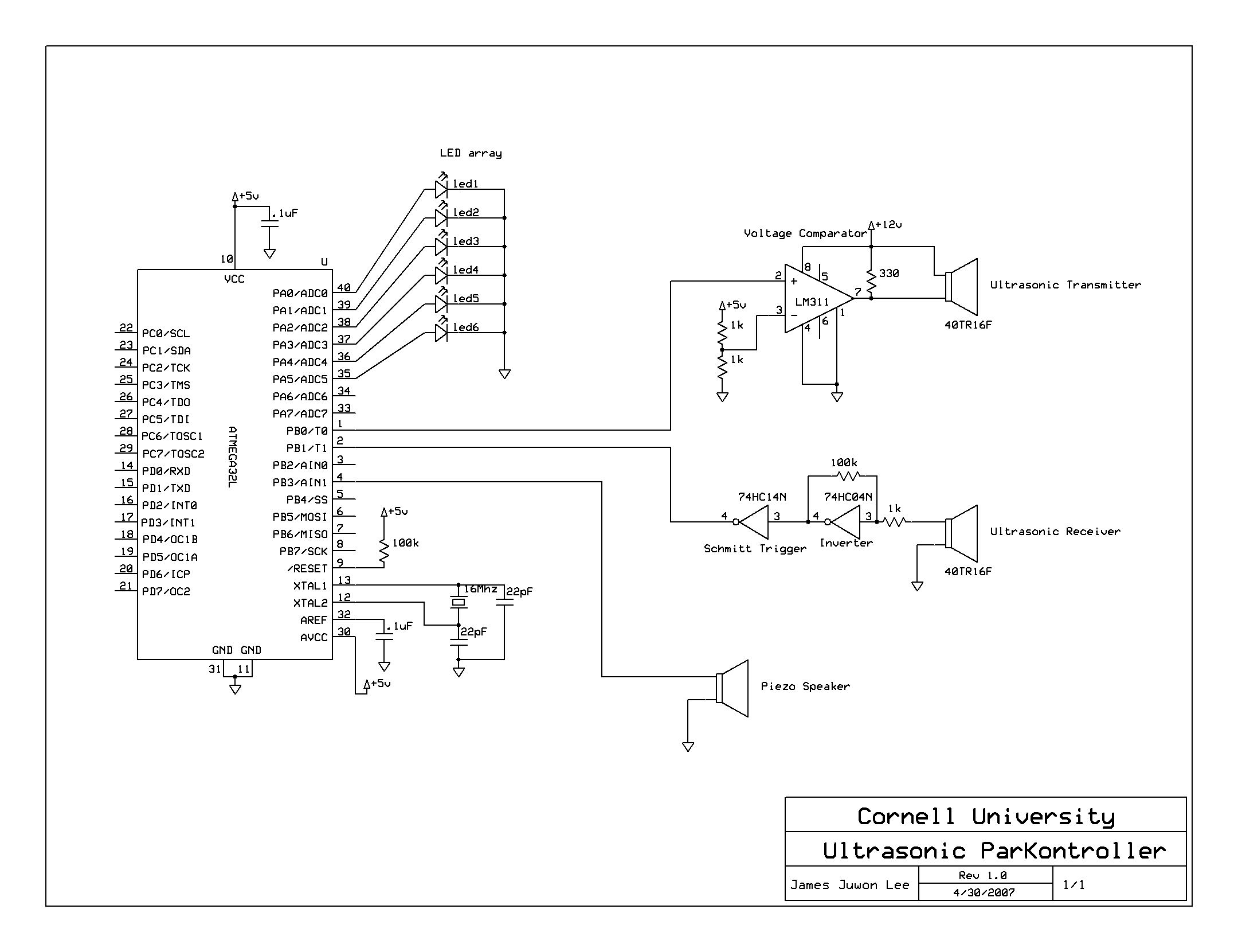
Ultrasonic Parking controller
A series of five short pulses blasted by the microcontroller only has 5V amplitude, which will be attenuated down to less than 20 mV when received by the receiver circuit. Hence, LM311 voltage comparator was used for signal amplification before...
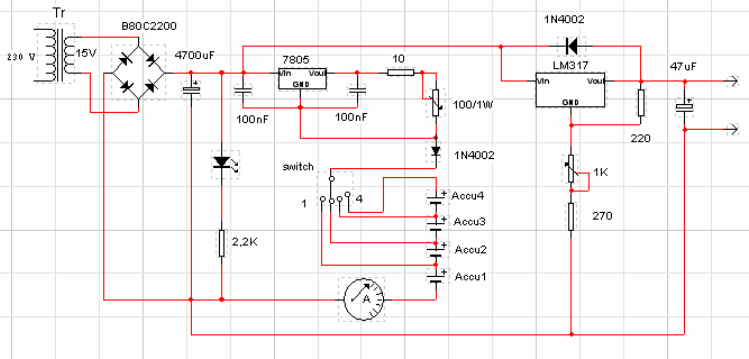
Batteries charger & PSU - ideal for digital camerass
This circuit was designed for digital cameras, which are known to have significant power consumption. For instance, the Minolta E223 camera requires approximately 800 mA. In practice, this demand can be met using a mains power supply or high-capacity NiMH...

General use Preamplifier with 2N3904
Most audio amplifier systems must have preamplifiers with many different characteristics. These include high-gain linear response for magnetic microphones, low-gain linear response for tuners, and high-gain RIAA equalization for magnetic phone cartridges. To meet this broad requirement, most amplifier designers...
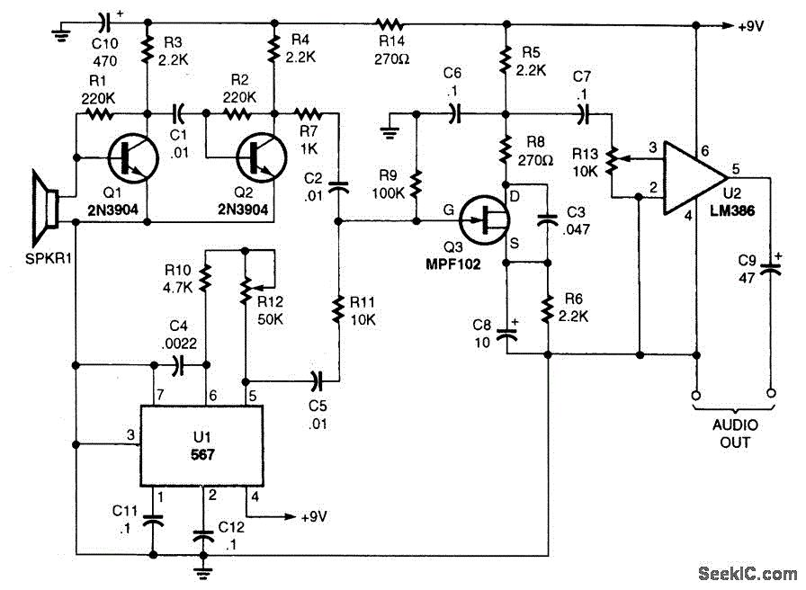
ULTRASONIC SOUND RECEIVER
The performance of this sensitive ultrasonic receiver is impressive. It allows users to listen to various sources of ultrasonic sounds, including bugs, bats, and engines. The circuit utilizes a piezo tweeter as an ultrasonic microphone, with amplifier stages Q1 and...
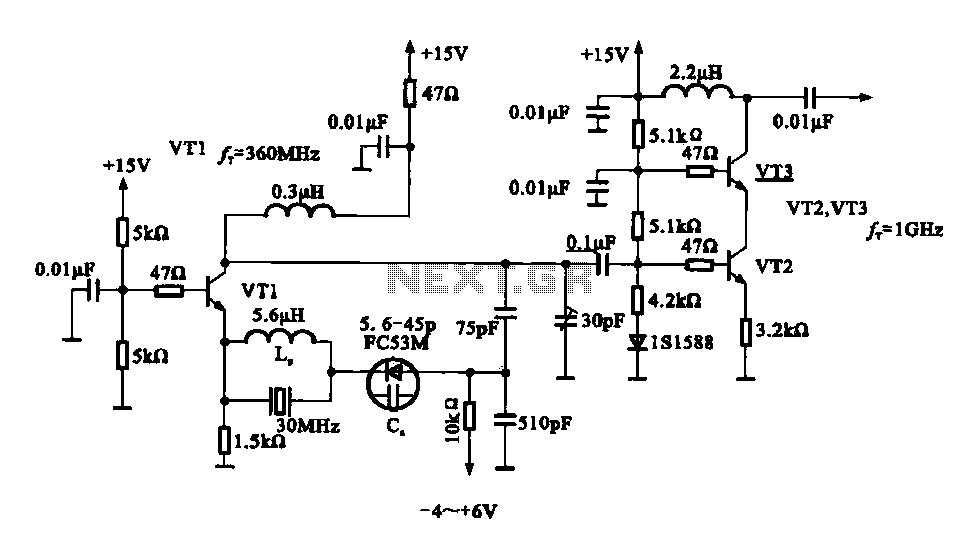
A variable frequency oscillating circuit transistor
A variable frequency oscillator transistor circuit, primarily functioning as an oscillator, incorporates a crystal resonator and a varactor diode. The output is amplified, typically used for generating high-frequency signals. This 30 MHz transistor circuit features an inductor (LP) connected to...