


Wein Bridge Oscillator using ic 741 op amp
#Wein Bridge Oscillator
#IC 741
#op amp
#sine wave
#audio frequency
#high stability
#sine wave generator
#local oscillator
#periodic signal
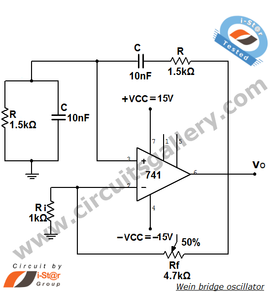
Description: The Wien bridge oscillator is a high-stability audio frequency sine wave oscillator known for its simplicity. An oscillator is defined as a circuit that generates periodic electric signals, such as sine waves or square waves. Applications of oscillators include sine wave generators and local oscillators for synchronous receivers. This discussion focuses on the Wien bridge oscillator utilizing the 741 operational amplifier (op-amp) IC, which operates as a low-frequency oscillator. In this configuration, the op-amp functions in a non-inverting amplifier mode, and the feedback network does not need to provide any phase shift. The circuit can be conceptualized as a Wien bridge with a series RC network in one arm and a parallel RC network in the adjacent arm. Resistors Ri and Rf are connected in the remaining two arms. At the resonant frequency (ω₀), the inverting and non-inverting input voltages are equal and in phase, resulting in the cancellation of the negative feedback signal by the positive feedback, which facilitates oscillation. Circuit analysis reveals that the feedback factor β equals 1/3 at the frequency of oscillation. For sustained oscillation, the amplifier must have a gain of 3, ensuring that the loop gain reaches unity.
The Wien bridge oscillator circuit is characterized by its unique configuration that enables it to produce a stable sine wave output. The operational amplifier (741) is pivotal in this design, as it amplifies the signal while maintaining the necessary phase relationships for oscillation. The circuit typically incorporates a combination of resistors and capacitors to form the necessary RC networks. The series RC network is designed to introduce a specific time constant that, in conjunction with the parallel RC network, defines the frequency of oscillation.
In the Wien bridge oscillator, the resistors Ri and Rf serve as part of the feedback loop, which is crucial for determining the gain of the amplifier. The feedback factor β of 1/3 indicates that for every unit of output, one-third is fed back into the inverting input of the op-amp. This feedback mechanism is essential for achieving the condition of sustained oscillation, where the loop gain must equal one.
The selection of resistors and capacitors in the circuit directly influences the frequency of the generated sine wave. By adjusting the values of these components, the oscillation frequency can be fine-tuned for specific applications, making the Wien bridge oscillator versatile in various electronic applications. Additionally, the circuit's design allows for easy implementation and modification, contributing to its popularity in audio frequency generation tasks.
Overall, the Wien bridge oscillator is an effective solution for generating stable sine waves, with its operational amplifier configuration providing both simplicity and reliability in electronic design.Wien bridge oscillator is an audio frequency sine wave oscillator of high stability and simplicity. Before that let us see what is oscillator An oscillator is a circuit that produces periodic electric signals such as sine wave or square wave. The application of oscillator includes sine wave generator, local oscillator for synchronous receivers et
c. Here we are discussing wein bridge oscillator using 741 op amp IC. It is a low frequency oscillator. The op-amp used in this oscillator circuit is working as non-inverting amplifier mode. Here the feedback network need not provide any phase shift. The circuit can be viewed as a wien bridge with a series RC network in one arm and parallel RC network in the adjoining arm. Resistors Ri and Rf are connected in the remaining two arms. At resonant frequency ( ’o), the inverting and non-inverting input voltages will be equal and in-phase so that the negative feedback signal will be cancelled out by the positive feedback causing the circuit to oscillate.
From the analysis of the circuit, it can be seen that the feedback factor ²= 1/3 at the frequency of oscillation. Therefore for sustained oscillation, the amplifier must have a gain of 3 so that the loop gain becomes unity.
The Wien bridge oscillator circuit is characterized by its unique configuration that enables it to produce a stable sine wave output. The operational amplifier (741) is pivotal in this design, as it amplifies the signal while maintaining the necessary phase relationships for oscillation. The circuit typically incorporates a combination of resistors and capacitors to form the necessary RC networks. The series RC network is designed to introduce a specific time constant that, in conjunction with the parallel RC network, defines the frequency of oscillation.
In the Wien bridge oscillator, the resistors Ri and Rf serve as part of the feedback loop, which is crucial for determining the gain of the amplifier. The feedback factor β of 1/3 indicates that for every unit of output, one-third is fed back into the inverting input of the op-amp. This feedback mechanism is essential for achieving the condition of sustained oscillation, where the loop gain must equal one.
The selection of resistors and capacitors in the circuit directly influences the frequency of the generated sine wave. By adjusting the values of these components, the oscillation frequency can be fine-tuned for specific applications, making the Wien bridge oscillator versatile in various electronic applications. Additionally, the circuit's design allows for easy implementation and modification, contributing to its popularity in audio frequency generation tasks.
Overall, the Wien bridge oscillator is an effective solution for generating stable sine waves, with its operational amplifier configuration providing both simplicity and reliability in electronic design.Wien bridge oscillator is an audio frequency sine wave oscillator of high stability and simplicity. Before that let us see what is oscillator An oscillator is a circuit that produces periodic electric signals such as sine wave or square wave. The application of oscillator includes sine wave generator, local oscillator for synchronous receivers et
c. Here we are discussing wein bridge oscillator using 741 op amp IC. It is a low frequency oscillator. The op-amp used in this oscillator circuit is working as non-inverting amplifier mode. Here the feedback network need not provide any phase shift. The circuit can be viewed as a wien bridge with a series RC network in one arm and parallel RC network in the adjoining arm. Resistors Ri and Rf are connected in the remaining two arms. At resonant frequency ( ’o), the inverting and non-inverting input voltages will be equal and in-phase so that the negative feedback signal will be cancelled out by the positive feedback causing the circuit to oscillate.
From the analysis of the circuit, it can be seen that the feedback factor ²= 1/3 at the frequency of oscillation. Therefore for sustained oscillation, the amplifier must have a gain of 3 so that the loop gain becomes unity.
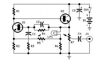
1KHZ Sine Wave Generator Circuit
Set R5 to read 1V RMS on an audio millivoltmeter connected to the output with R7 rotated fully clockwise, or to view a sine wave of 2.828V peak-to-peak amplitude on the oscilloscope. An audio amplifier is an electronic device that...
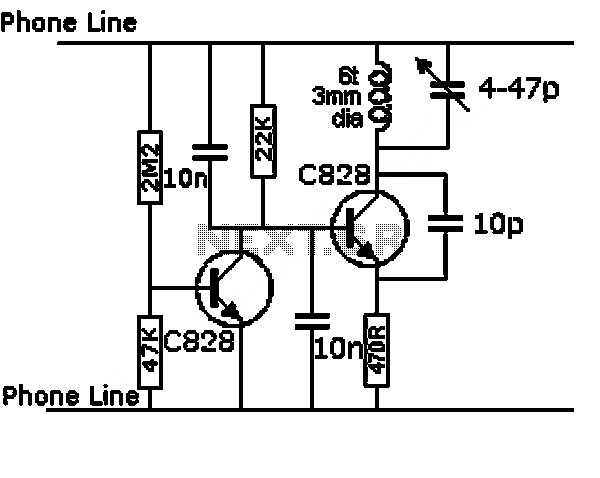
tuned sine wave oscillator circuit
This design circuit is intended for sine wave oscillators, providing both sine and square wave outputs across a frequency range from below 20 Hz to above 20 KHz. The oscillation frequency can be easily adjusted by changing a single resistor....
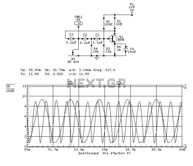
Low Frequency Sine wave Generators Schematic
The two circuits illustrate the generation of low-frequency sine waves by shifting the phase of the signal through an RC network, enabling oscillation when the total phase shift reaches 360 degrees. The transistor circuit on the right produces a reasonable...
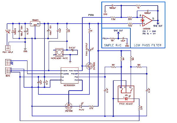
digital sine wave synthesis
In an analog world, converting digital values to their analog equivalents is often necessary when using microcontrollers. Many low-cost microcontrollers lack built-in hardware digital-to-analog converters (DACs), but most feature an 8-bit or 16-bit timer capable of generating Pulse Width Modulation...
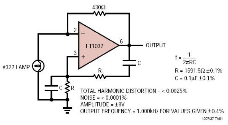
LT1007/LT1037 Ultrapure 1kHz Sine Wave Generator
A lamp provides amplitude stability while the very low noise amplifier generates a pure sine wave signal. The resistance and capacitance values determine the oscillator frequency, while the feedback resistor regulates the lamp current and output amplitude.
The circuit described consists...
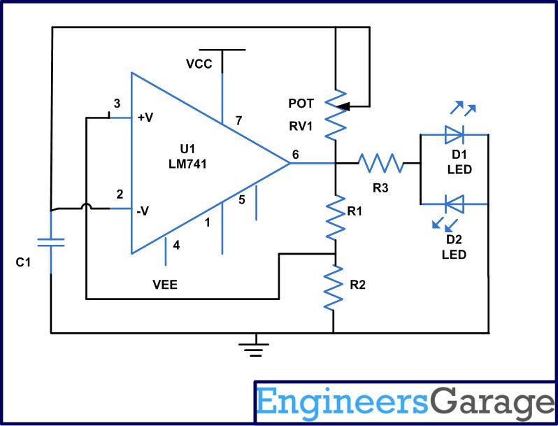
Astable multivibrator using op amp negative feedback circuits
An astable multivibrator is an electronic device that continuously alternates between two states in its output. When one state is high, the other is low. This characteristic is useful for generating a continuous stream of pulses without the need for...
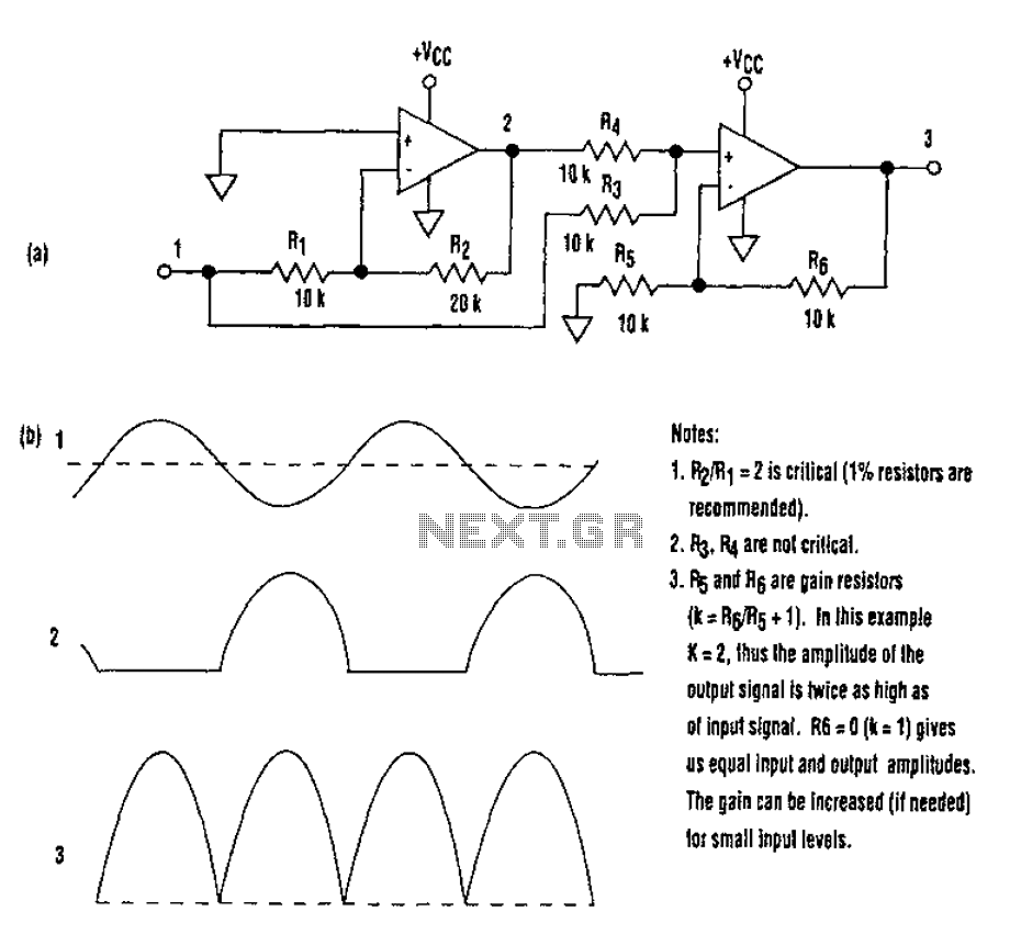
Non-diode rectifier
When utilizing a single-supply operational amplifier in a bipolar signal environment, achieving simple functions can be challenging. This often necessitates the inclusion of additional operational amplifiers and other electronic components. The advantages of this configuration can be observed in the...
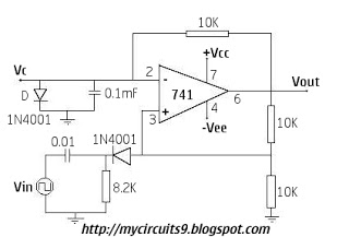
OP AMP BASED MONOSTABLE MULTIVIBRATOR 741
The circuit remains in a stable state until a triggering signal is applied to its input. Upon receiving the triggering signal, the output transitions from a stable state to a quasi-stable state and returns after a specified time period, generating...
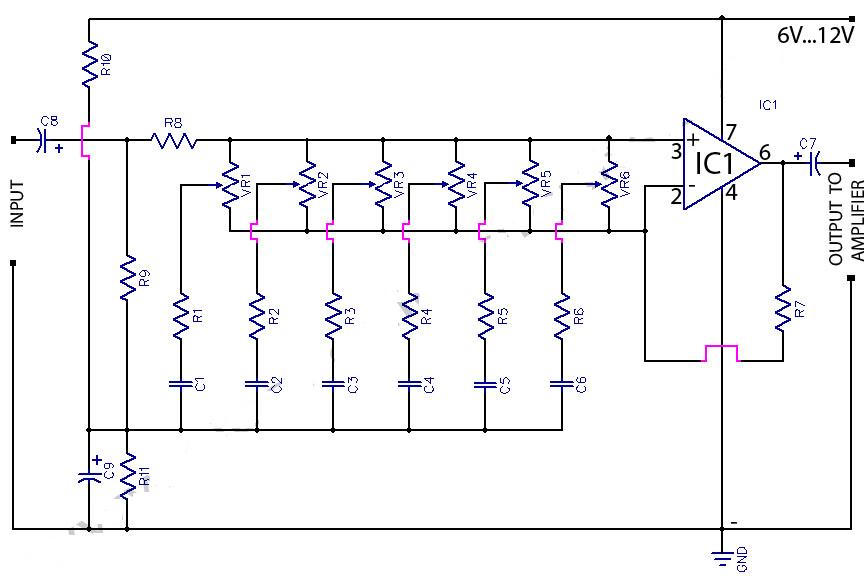
6 graphic equaliser circuit 741 op amp
This circuit is a six-band graphic equalizer that allows modification of sound across low, mid, and high frequencies using an IC 741 operational amplifier. It enables management and mixing of frequencies and tones as desired. The audible frequency spectrum is...