


0-28 Volt 6A regulated variable power supply circuit with 7815 and two 2n3055
#variable power supply
#voltage regulator
#2N3055
#7815
#high current
#regulated output
#overload protection
#thermal protection
#6A output
#28V
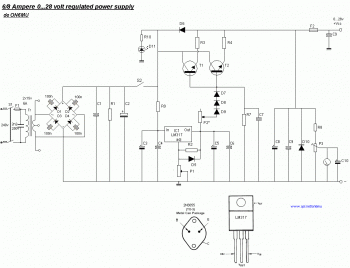
Description: This is a simple power supply that provides a reliable and clear regulated output voltage ranging from 0 to 28 volts with a maximum current of 6 to 8 amperes. Utilizing two 2N3055 transistors allows for doubling the output current. The 7815 voltage regulator is designed to activate during brief circuit conditions, overload situations, or thermal overheating. Protection is provided by fuses located in the primary section of the transformer and an additional fuse (F2) at the output. The rectified voltage is calculated as 30 volts multiplied by the square root of 2, resulting in approximately 42.30 volts measured across capacitor C1. Therefore, all capacitors should be rated for at least 50 volts. It is important to note that if one of the transistors fails, the output voltage may reach around 42 volts. A potentiometer (P1) is included to adjust the output voltage from 0 to 28 volts. The LM317 voltage regulator has a minimum output voltage of 1.2 volts. To achieve a zero output voltage, three diodes (D7, D8, and D9) are connected from the output of the LM317 to the base of the 2N3055 transistors. The maximum output voltage of the LM317 is 30 volts; however, with the diodes, the output voltage is approximately 28.2 volts (30 volts minus 3 times 0.6 volts). Another potentiometer (P2) allows for setting the maximum output current at +Vcc. When using a 100-ohm, 1-watt variable resistor, the output current is limited to approximately 3 amps at 47 ohms and around 1 amp at 100 ohms.
The described power supply circuit is a versatile solution for applications requiring adjustable voltage and current. The use of two 2N3055 transistors in a push-pull configuration enhances the output current capability, making it suitable for powering devices that demand higher current levels. The 7815 voltage regulator serves as a fundamental component for maintaining a stable output voltage under varying load conditions, while the fuses provide essential protection against overcurrent scenarios, ensuring the longevity and reliability of the power supply.
The rectification stage is crucial, as it converts the AC voltage from the transformer into a stable DC voltage. The calculated rectified voltage of approximately 42.30 volts necessitates the use of capacitors rated for at least 50 volts to prevent breakdown and ensure safe operation. The inclusion of diodes in the output stage not only aids in achieving the desired voltage range but also protects the transistors from potential damage due to excessive voltage.
The adjustable output voltage, facilitated by the potentiometer P1, allows users to fine-tune the voltage to meet specific requirements, making this power supply suitable for various electronic projects. The current limiting feature provided by potentiometer P2 is particularly beneficial in preventing damage to both the power supply and connected loads, as it allows users to set a safe operating current.
In summary, this power supply circuit is designed with both functionality and safety in mind, providing a robust solution for a wide range of electronic applications. The careful selection of components and design considerations ensures reliable operation, making it an excellent choice for hobbyists and professionals alike.This is definitely an simple to create power supply which has reliable, clear and regulator 0 to 28 Volt 6/8 Ampere output voltage. By using two 2N3055 transistor, you`ll get two times the amount of electric current. Although the 7815 power regulator is going to kick in on brief circuit, overload and thermal overheating, the fuses within the prima
ry section of the transformer and also the fuse F2 in the output will protected your power supply. The rectified voltage of: 30 volt x SQR2 = 30 x 1. 41 = 42. 30 volt measured on C1. So all capacitors ought to be rated at 50 volts. Caution: 42 volt is the voltage that might be around the output if one of the transistors ought to blow. P1 allows you to `regulate` the output voltage to anything between 0 and 28 volts. The LM317 lowest voltage is 1. 2 volt. To have a zero voltage around the output I`ve put 3 diodes D7, D8 and D9 on the output of the LM317 to the base of the 2N3055 transistors.
The LM317 optimum output voltage is 30 volts, but applying the diodes D7, D8 & D9 the output voltage is approx 30v - (3x 0. 6v) = 28. 2volt. P2 will certainly let you to set the limit of the optimum available electric current at the output +Vcc.
When using a 100 Ohm / 1 watt variable resistor the current is limited to approx. 3 Amps @ 47 Ohm and +- 1 Amp @ 100 Ohms.
The described power supply circuit is a versatile solution for applications requiring adjustable voltage and current. The use of two 2N3055 transistors in a push-pull configuration enhances the output current capability, making it suitable for powering devices that demand higher current levels. The 7815 voltage regulator serves as a fundamental component for maintaining a stable output voltage under varying load conditions, while the fuses provide essential protection against overcurrent scenarios, ensuring the longevity and reliability of the power supply.
The rectification stage is crucial, as it converts the AC voltage from the transformer into a stable DC voltage. The calculated rectified voltage of approximately 42.30 volts necessitates the use of capacitors rated for at least 50 volts to prevent breakdown and ensure safe operation. The inclusion of diodes in the output stage not only aids in achieving the desired voltage range but also protects the transistors from potential damage due to excessive voltage.
The adjustable output voltage, facilitated by the potentiometer P1, allows users to fine-tune the voltage to meet specific requirements, making this power supply suitable for various electronic projects. The current limiting feature provided by potentiometer P2 is particularly beneficial in preventing damage to both the power supply and connected loads, as it allows users to set a safe operating current.
In summary, this power supply circuit is designed with both functionality and safety in mind, providing a robust solution for a wide range of electronic applications. The careful selection of components and design considerations ensures reliable operation, making it an excellent choice for hobbyists and professionals alike.This is definitely an simple to create power supply which has reliable, clear and regulator 0 to 28 Volt 6/8 Ampere output voltage. By using two 2N3055 transistor, you`ll get two times the amount of electric current. Although the 7815 power regulator is going to kick in on brief circuit, overload and thermal overheating, the fuses within the prima
ry section of the transformer and also the fuse F2 in the output will protected your power supply. The rectified voltage of: 30 volt x SQR2 = 30 x 1. 41 = 42. 30 volt measured on C1. So all capacitors ought to be rated at 50 volts. Caution: 42 volt is the voltage that might be around the output if one of the transistors ought to blow. P1 allows you to `regulate` the output voltage to anything between 0 and 28 volts. The LM317 lowest voltage is 1. 2 volt. To have a zero voltage around the output I`ve put 3 diodes D7, D8 and D9 on the output of the LM317 to the base of the 2N3055 transistors.
The LM317 optimum output voltage is 30 volts, but applying the diodes D7, D8 & D9 the output voltage is approx 30v - (3x 0. 6v) = 28. 2volt. P2 will certainly let you to set the limit of the optimum available electric current at the output +Vcc.
When using a 100 Ohm / 1 watt variable resistor the current is limited to approx. 3 Amps @ 47 Ohm and +- 1 Amp @ 100 Ohms.
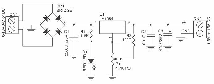
1.2 - 15V/3A variable and regulated PS
This kit provides a variable output power supply ranging from 1.2 to 15 V @ 3 A. It uses Low Dropout Positive Regulator LM1084 in TO220 package for delivering variable output voltage. Input - 18 VAC/DC. Output - variable output...
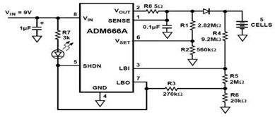
Micropower Linear Voltage Regulator in the Battery Charger Circuit
The ADM666A application note provides a detailed explanation of a low-cost battery charger circuit, including maximum output voltage, charge termination voltage calculation, battery voltage level monitoring, and circuit efficiency optimization. The ADM666A utilizes an NPN transistor and a P-channel FET....
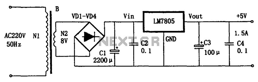
LM7805 + 5V power supply configuration
The circuit illustrated in the figure provides an output voltage of +5V and an output current of 1.5A. It comprises a power transformer, a bridge rectifier circuit consisting of diodes D1 to D4, and filter capacitor C1. Additionally, capacitors C2...
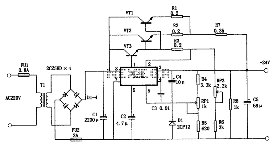
5G14D + 24V 1.9A power supply
The circuit illustrated in the figure is a +24V, 1.9A power supply design. It employs the 5G14D domestic integrated voltage regulator as the core component, supported by three external power transistors. While the 5G14D voltage regulator has a rated current...
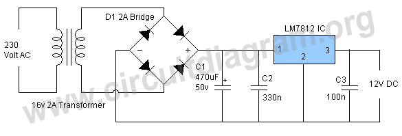
12v power supply circuit
This project involves a straightforward and practical 12V power supply circuit utilizing the LM7812 integrated circuit (IC). The LM7812 is a three-terminal fixed voltage regulator IC housed in a TO-220 package. It incorporates several built-in features such as thermal shutdown,...
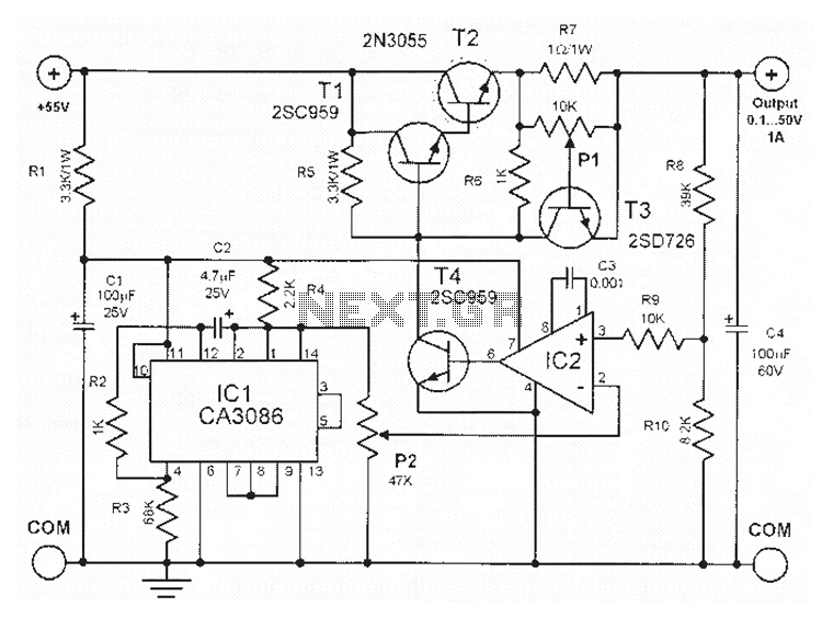
0-50V 1A power supply with CA3086
This power supply circuit is highly stabilized that its output voltage will drop only 0.005% even though the load changes from 0 to 100%. Another excellent capability is that the output voltage will change only by 0.01% if the input...

0-28V Variable power supply II
Another method of using opamps to regulate a power supply is shown below. The power transformer requires an additional winding to supply the op-amps with a bipolar voltage (+/- 8 volts), and the negative voltage is also used to generate...
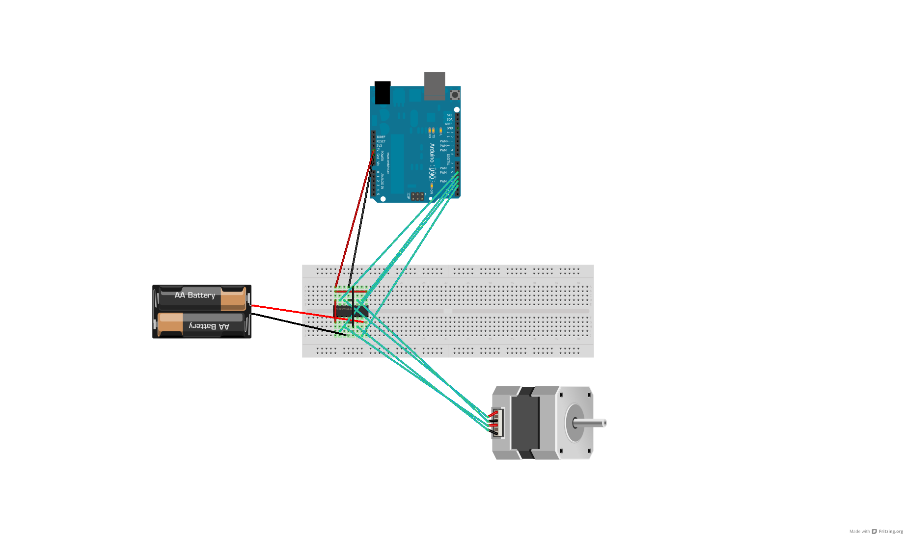
Voltage regulator or resistors to change voltages for motors
After conducting some research, it was found that voltage can be adjusted using either a voltage regulator chip or resistors. Several scenarios require reducing the voltage for motors, prompting a question about the appropriate method for each application. An H-Bridge...
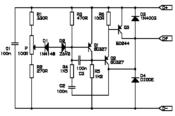
BMW R Series Motorcycle Regulator Schematic
Correctly adjusted, the voltage on the pot wiper is slightly less than half D+ (appx. 0.47*D+) and Q1 will conduct if (D+)-(Vp) > 6.2 + 0.7 + 0.7, or 0.53*(D+) > 7.6V, (D+) > 14.3V. If D+ is lower than...