


1,5-15V 500mA Power Supply
#variable power supply
#voltage regulator
#500mA
#potentiometer
#overload protection
#buzzer alarm
#low cost
#1.5-15V
#stabilization
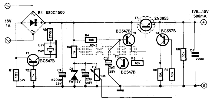
Description: This simple variable power supply circuit has a low production cost and delivers an output voltage between 1.5 V and 15 V with a 500 mA maximum current. Its stabilization is better than 2% if the current consumption does not exceed 350 mA. The variation of the power supply voltage can be made with a potentiometer and when overloading occurs, a buzzer sounds an alarm. More: T4 compares the P1 slider voltage with the output voltage. Then the P1 slider voltage is 0.65 V higher than the adjusted voltage, T2 opens, which stops the T3-T5 Darlington base current. The 18V, 1A transformer voltage must be filtered with B1 and C1. When the output current is more than 500 mA, the Bz1 starts the alarm (overloading). Bz1 must be a 24 V type, auto-oscillating.
The described variable power supply circuit is designed for low-cost applications while providing a range of output voltages from 1.5 V to 15 V, with a maximum current output of 500 mA. The circuit employs a potentiometer (P1) to allow for adjustable output voltage, enabling users to set the desired voltage level within the specified range. The stability of the output voltage is maintained within a tolerance of 2% as long as the load current remains below 350 mA, ensuring reliable performance for various applications.
The operational mechanism involves a feedback control system where transistor T4 monitors the voltage at the P1 slider compared to the output voltage. If the slider voltage exceeds the output voltage by 0.65 V, transistor T2 is triggered to open, effectively cutting off the base current to the Darlington pair formed by transistors T3 and T5. This configuration helps to regulate the output voltage by controlling the current flow through the power transistors, thus preventing over-voltage conditions.
The input power to the circuit is provided by an 18V, 1A transformer, which requires filtering to smooth out the rectified voltage. Capacitor C1 and diode B1 are employed for this purpose, ensuring that the output voltage remains stable and free from ripple.
In the event of an overload condition, where the output current exceeds 500 mA, an alarm is activated by buzzer Bz1. This buzzer is specified to operate at 24 V and is of the auto-oscillating type, providing an audible signal to alert users of the overload condition. This feature enhances the safety and usability of the power supply circuit, making it suitable for various electronic projects and applications where adjustable and stable voltage is required.This simple variable power supply circuit has a low production cost and delivers an output voltage between 1,5 V and 15 V with a 500 mA maximum current. Its stabilization is better than 2% if the current consumption do not exceed 350 mA. The variation of the power supply voltage can be made with a potentiometer and when overloading occurs a buzzer sounds a alarm.
T4 compairs the P1 slider voltage with the output voltage. Then the P1 slider voltage is 0,65 V higher than the adjusted voltage, T2 opens, which stops the T3-T5 Darlington base current. The 18V, 1A transformer voltage must be filtered with B1 and C1. When the output current is more then 500 mA, the Bz1 starts the alarm (overloading). Bz1 must be a 24 V type, auto-oscillating.
The described variable power supply circuit is designed for low-cost applications while providing a range of output voltages from 1.5 V to 15 V, with a maximum current output of 500 mA. The circuit employs a potentiometer (P1) to allow for adjustable output voltage, enabling users to set the desired voltage level within the specified range. The stability of the output voltage is maintained within a tolerance of 2% as long as the load current remains below 350 mA, ensuring reliable performance for various applications.
The operational mechanism involves a feedback control system where transistor T4 monitors the voltage at the P1 slider compared to the output voltage. If the slider voltage exceeds the output voltage by 0.65 V, transistor T2 is triggered to open, effectively cutting off the base current to the Darlington pair formed by transistors T3 and T5. This configuration helps to regulate the output voltage by controlling the current flow through the power transistors, thus preventing over-voltage conditions.
The input power to the circuit is provided by an 18V, 1A transformer, which requires filtering to smooth out the rectified voltage. Capacitor C1 and diode B1 are employed for this purpose, ensuring that the output voltage remains stable and free from ripple.
In the event of an overload condition, where the output current exceeds 500 mA, an alarm is activated by buzzer Bz1. This buzzer is specified to operate at 24 V and is of the auto-oscillating type, providing an audible signal to alert users of the overload condition. This feature enhances the safety and usability of the power supply circuit, making it suitable for various electronic projects and applications where adjustable and stable voltage is required.This simple variable power supply circuit has a low production cost and delivers an output voltage between 1,5 V and 15 V with a 500 mA maximum current. Its stabilization is better than 2% if the current consumption do not exceed 350 mA. The variation of the power supply voltage can be made with a potentiometer and when overloading occurs a buzzer sounds a alarm.
T4 compairs the P1 slider voltage with the output voltage. Then the P1 slider voltage is 0,65 V higher than the adjusted voltage, T2 opens, which stops the T3-T5 Darlington base current. The 18V, 1A transformer voltage must be filtered with B1 and C1. When the output current is more then 500 mA, the Bz1 starts the alarm (overloading). Bz1 must be a 24 V type, auto-oscillating.

variable power supply with l200
The voltage output is controlled by a 10K variable resistor. The output voltage range is approximately 3 to 15 volts, with a current range of about 10mA minimum and 2A maximum. When the current limit is reached, the output voltage...
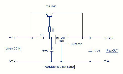
Increasing Regulator Current
Although the 78xx series of voltage regulators are available with different current outputs, you can boost the available current output with this circuit. A power transistor is used to supply extra current to the load, maintaining a constant voltage. Currents...
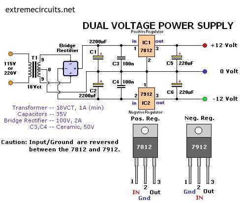
Dual Voltage 12V Power Supply
The following circuit diagram of a dual voltage power supply can be used for miscellaneous applications. It requires a few components to build. The most important components of this circuit are regulators: 1: (AN) 7812 and 2: (AN) 7912. AN7812...
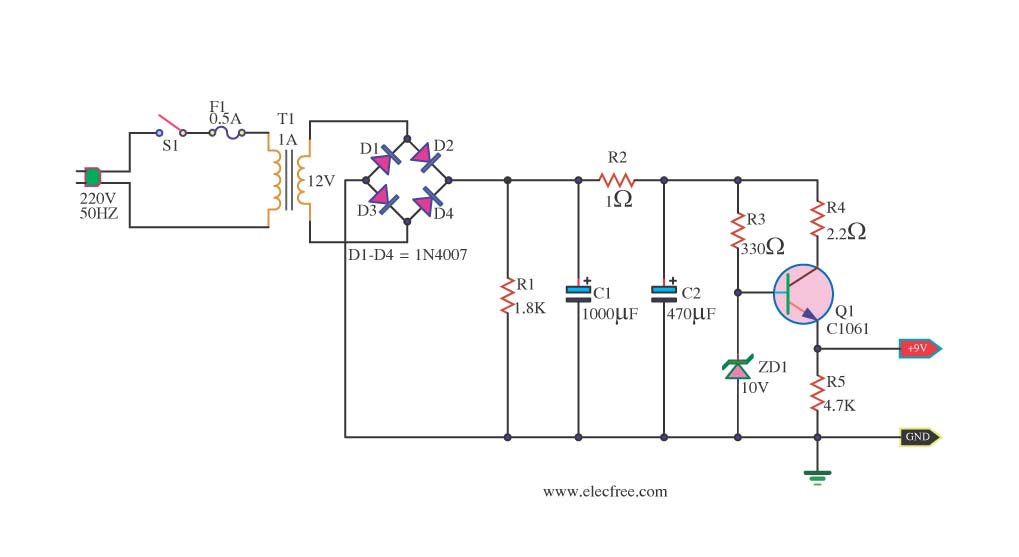
DC Power Supply 9 volt using TIP31 transistor
This is a DC power supply circuit designed to regulate 9 volts and provide a current output ranging from 1 amp to 2 amps. The circuit utilizes a modified TIP31 transistor, although alternative transistors such as TIP41, MJE3055, or 2SC1061...
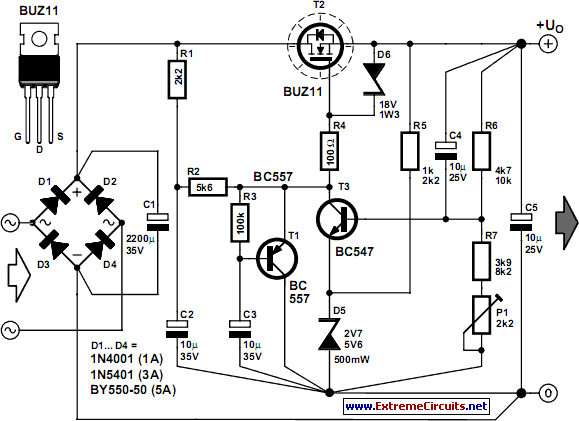
Stable Filament Power Supply Circuit
The circuit diagram illustrates a voltage regulator designed from discrete components to meet specific voltage requirements. It provides two sets of component values for output voltages of 6.3 V (upper) and 12.6 V (lower). The components used include BC547 and...

15v variable power supply circuit
This 15V variable power supply electronic project is designed using 2N3055 transistors. The output voltage of this variable power supply can be adjusted in the range between 1.5 and 15 volts. This 2N3055 15V variable power supply can provide a...
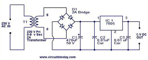
5V power supply using 7805 IC with circuit diagram
A 5V power supply using IC 7805 is designed and explained with a neat circuit diagram.
The circuit for a 5V power supply utilizing the IC 7805 voltage regulator is a straightforward and efficient design that provides a stable output voltage...
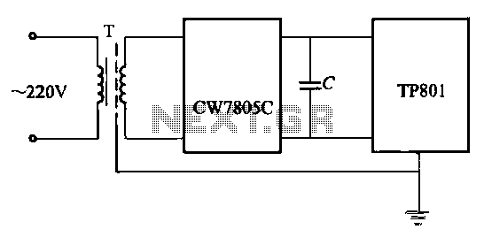
MCU power supply wiring portion
High-precision voltage regulator, isolation transformer with the correct wiring, and low-pass filter to enhance the electrical noise immunity of the source portion. The wiring in Figures 20-48 and 20-49 is illustrated in the figures. Chokes (L1, L2) should have an...
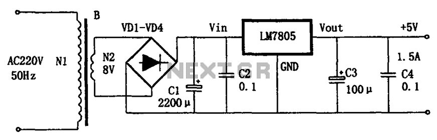
LM7805 + 5V power supply configuration
The circuit illustrated in the figure provides an output voltage of +5V and an output current of 1.5A. It comprises a power transformer, a bridge rectifier circuit consisting of diodes D1 to D4, and filter capacitor C1. Additionally, capacitors C2...