


1.5 - 35 Volt DC Regulated Power Supply
#regulated
#voltage
#DC
#1.5V-35V
#circuit diagram
#projects
#small power supply
#electronics
#DIY
#voltage regulation
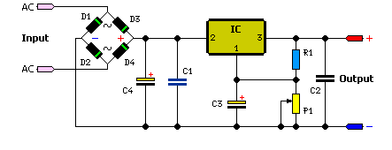
Description: The simple method to power your projects is illustrated in the circuit diagram of a regulated power supply. This compact power supply delivers a stable voltage.
This regulated power supply circuit is designed to convert an unregulated input voltage into a stable output voltage suitable for powering various electronic projects. The circuit typically consists of a transformer, a rectifier, a filter capacitor, and a voltage regulator.
1. **Transformer**: The transformer steps down the input AC voltage to a lower AC voltage level, which is necessary for the subsequent rectification process. The turns ratio of the transformer must be chosen based on the desired output voltage and the specifications of the project.
2. **Rectifier**: The rectifier converts the stepped-down AC voltage into pulsating DC voltage. This is usually achieved using a bridge rectifier configuration, which consists of four diodes arranged in a bridge layout. This configuration allows for full-wave rectification, improving efficiency and reducing ripple voltage.
3. **Filter Capacitor**: After rectification, the output still contains some ripple voltage. A filter capacitor is connected in parallel with the load to smooth out this ripple, providing a more stable DC voltage. The capacitance value should be selected based on the load current and the acceptable ripple voltage.
4. **Voltage Regulator**: The last stage in the circuit is the voltage regulator, which ensures that the output voltage remains constant despite variations in load current or input voltage. Common voltage regulators include the 7805 for +5V output or the LM317 for adjustable output voltages. The regulator may require additional capacitors at the input and output to maintain stability.
Overall, this regulated power supply circuit is essential for providing reliable power to various electronic devices and projects, ensuring that they operate within their specified voltage ranges. Proper selection of components and careful design considerations will enhance the performance and reliability of the power supply.The easy way to power your projects Here is the circuit diagram of regulated power supply. It is a small power supply that provides a regulated voltage, a..
This regulated power supply circuit is designed to convert an unregulated input voltage into a stable output voltage suitable for powering various electronic projects. The circuit typically consists of a transformer, a rectifier, a filter capacitor, and a voltage regulator.
1. **Transformer**: The transformer steps down the input AC voltage to a lower AC voltage level, which is necessary for the subsequent rectification process. The turns ratio of the transformer must be chosen based on the desired output voltage and the specifications of the project.
2. **Rectifier**: The rectifier converts the stepped-down AC voltage into pulsating DC voltage. This is usually achieved using a bridge rectifier configuration, which consists of four diodes arranged in a bridge layout. This configuration allows for full-wave rectification, improving efficiency and reducing ripple voltage.
3. **Filter Capacitor**: After rectification, the output still contains some ripple voltage. A filter capacitor is connected in parallel with the load to smooth out this ripple, providing a more stable DC voltage. The capacitance value should be selected based on the load current and the acceptable ripple voltage.
4. **Voltage Regulator**: The last stage in the circuit is the voltage regulator, which ensures that the output voltage remains constant despite variations in load current or input voltage. Common voltage regulators include the 7805 for +5V output or the LM317 for adjustable output voltages. The regulator may require additional capacitors at the input and output to maintain stability.
Overall, this regulated power supply circuit is essential for providing reliable power to various electronic devices and projects, ensuring that they operate within their specified voltage ranges. Proper selection of components and careful design considerations will enhance the performance and reliability of the power supply.The easy way to power your projects Here is the circuit diagram of regulated power supply. It is a small power supply that provides a regulated voltage, a..
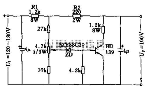
100v / 10ma regulator circuit
The circuit features no-load and short circuit protection mechanisms. To accommodate short circuit conditions, it is necessary to increase resistors R1 and R2 to allow for power dissipation; for example, R1 can be set to 1.2kΩ with a power rating...
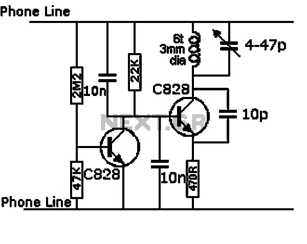
MAKING YOUR OWN REGULATED POWER SUPPLY
This document presents a basic electronics project focused on creating a regulated power supply. A regulated power supply is essential for various electronic circuits, as it provides a constant voltage necessary for their operation. Understanding how to construct a regulated...
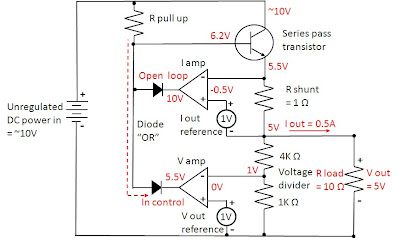
how does power supply regulate its
Most power supplies regulate either their output voltage or current at a constant level, depending on the load resistance relative to the power supply's output voltage and current settings. This can be summarized as follows: To accomplish this, most power...
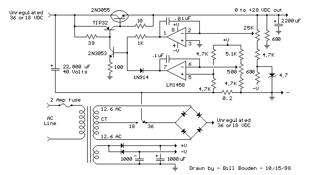
Current and Variable Voltage Power Supply
Another adjustment of application operational amplifiers to adapt a power supply is apparent below. The power supply requires an additional adjustment to supply the op-amps with a bipolar voltage (+/- 8 volts), and the negative voltage is also used to...
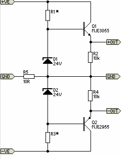
Simple Pre-Regulator
There will be many occasions when it is beneficial to utilize the P05 supply module sourced from a higher voltage supply. For instance, this could be advantageous when integrating balanced inputs.
The P05 supply module is designed to facilitate the conversion...
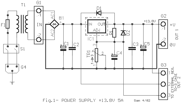
Electronics Projects Circuits
Over 1400 top electronics projects and electronic circuits with photos, datasheets, and easy-to-read schematics, along with explanations of how they work and how to build them.
The collection comprises a vast array of electronics projects suitable for enthusiasts and professionals alike....
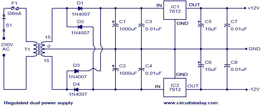
Regulated dual power supply circuit
The circuit described is a regulated dual power supply that provides +12V and -12V from the AC mains. Such a power supply is an essential tool for electronic hobbyists. The transformer T1 reduces the AC mains voltage, while diodes D1,...
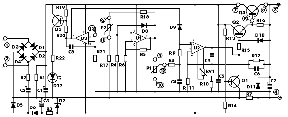
0-30 VDC Stabilized Power Supply with Current Control 0.002-3 A
The circuit begins with a step-down mains transformer featuring a secondary winding rated at 24 V/3 A, which connects across the input points at pins 1 and 2. The quality of the output supply is directly related to the transformer's...
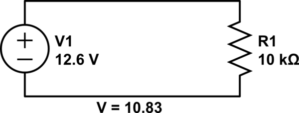
voltage Calculating current in a simple circuit
Connect a 12V fan to this circuit that consumes 70mA (0.07A), ensuring the circuit can supply at least that amount of current. There appears to be a misunderstanding regarding the analysis. The voltage drop across the resistor equals the voltage...