


12 volt switching power supply using ltc3810 5
#LTC3810-5
#switching regulator
#step-down converter
#12V power supply
#telecom
#automotive
#synchronous
#voltage regulator
#DC-DC converter
#high voltage
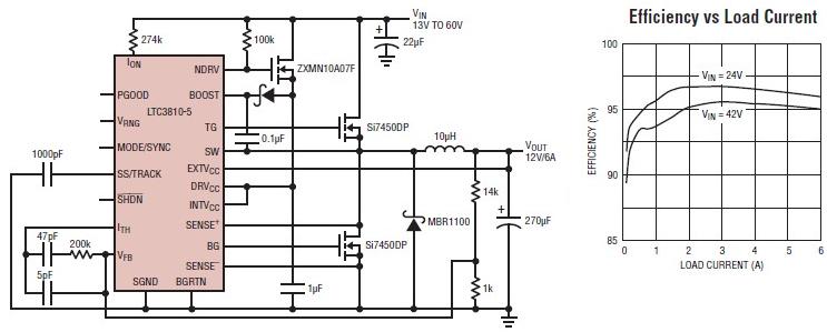
Description: The LTC3810-5 synchronous step-down switching regulator controller can be used to design a simple and efficient 12-volt switching power supply electronic project with minimal external components. This controller is capable of stepping down voltages from up to 60V, making it suitable for telecommunications and automotive applications. The LTC3810-5 employs a constant on-time valley current control architecture, allowing for very low duty cycles and accurate cycle-by-cycle current limiting without the need for a sense resistor. It features a precise internal reference that ensures 0.5% DC accuracy. A high bandwidth (25MHz) error amplifier provides rapid response to line and load transients. The design supports a maximum output current of 6 amperes with high efficiency exceeding 95 percent. The constant on-time current mode architecture includes cycle-by-cycle current limit protection, which is crucial for safeguarding high voltage power supplies. The circuit diagram illustrates that this 12-volt switching power supply requires only a few external components, making it ideal for compact power supply applications.
The LTC3810-5 synchronous step-down switching regulator controller is designed for high-performance applications where efficiency and reliability are paramount. This device is capable of managing input voltages up to 60V, which is particularly beneficial in environments where power supply voltages can vary significantly, such as in automotive or telecommunications systems. The architecture of the LTC3810-5 utilizes a constant on-time control method, which enhances the regulator's ability to maintain stable output voltages under varying load conditions.
One of the key features of this regulator is its cycle-by-cycle current limit protection. This feature is essential for preventing damage to the circuit during overload conditions, as it allows the controller to respond immediately to excessive current draw. The absence of a sense resistor simplifies the design, reduces component count, and minimizes power loss associated with current sensing.
The internal reference voltage of 0.5% accuracy ensures that the output voltage remains stable and within specified limits, which is critical for sensitive electronic applications. The high bandwidth error amplifier operates at 25MHz, allowing for quick adjustments to output voltage in response to sudden changes in load or input voltage, thus enhancing the overall performance of the power supply.
This power supply design can deliver a maximum output current of 6A while achieving efficiencies greater than 95%. Such performance is particularly advantageous in battery-powered applications or systems where thermal management is a concern, as it reduces wasted energy and heat generation.
The schematic of the 12-volt switching power supply demonstrates the simplicity of the design, requiring only a few external components, such as inductors, capacitors, and diodes, which contribute to a compact form factor. This makes the LTC3810-5 an excellent choice for applications where space is limited or where a lightweight power supply is necessary. Overall, the LTC3810-5 provides a robust solution for creating efficient and reliable switching power supplies across a variety of demanding applications.Using the LTC3810-5 synchronous step-down switching regulator controller can be designed a very easy and simple 12 volt switching power supply electronic project using few external electronic parts. LTC3810-5 synchronous step-down switching regulator controller can directly step-down voltages from up to 60V, making it ideal for telecom and automo
tive applications. The LTC3810-5 uses a constant on-time valley current control architecture to deliver very low duty cycles with accurate cycle-by-cycle current limit, without requiring a sense resistor. A precise internal reference provides 0. 5% DC accuracy. A high bandwidth (25MHz) error amplifier provides very fast line and load transient response. Large 1 © gate drivers This 12 volt switching power supply electronic project based on LTC3810-5 synchronous step-down switching regulator controller will support a maximum output current up to 6 amperes with a high efficiency, more than 95 percent.
Constant on-time current mode architecture provides accurate cycle-by-cycle current limit protection ”a feature that is very important for protecting the high voltage power As you can see in the circuit diagram, this 12 volt switching power supply circuit require few external electronic parts, thing that make it ideal for compact power supplies applications.
The LTC3810-5 synchronous step-down switching regulator controller is designed for high-performance applications where efficiency and reliability are paramount. This device is capable of managing input voltages up to 60V, which is particularly beneficial in environments where power supply voltages can vary significantly, such as in automotive or telecommunications systems. The architecture of the LTC3810-5 utilizes a constant on-time control method, which enhances the regulator's ability to maintain stable output voltages under varying load conditions.
One of the key features of this regulator is its cycle-by-cycle current limit protection. This feature is essential for preventing damage to the circuit during overload conditions, as it allows the controller to respond immediately to excessive current draw. The absence of a sense resistor simplifies the design, reduces component count, and minimizes power loss associated with current sensing.
The internal reference voltage of 0.5% accuracy ensures that the output voltage remains stable and within specified limits, which is critical for sensitive electronic applications. The high bandwidth error amplifier operates at 25MHz, allowing for quick adjustments to output voltage in response to sudden changes in load or input voltage, thus enhancing the overall performance of the power supply.
This power supply design can deliver a maximum output current of 6A while achieving efficiencies greater than 95%. Such performance is particularly advantageous in battery-powered applications or systems where thermal management is a concern, as it reduces wasted energy and heat generation.
The schematic of the 12-volt switching power supply demonstrates the simplicity of the design, requiring only a few external components, such as inductors, capacitors, and diodes, which contribute to a compact form factor. This makes the LTC3810-5 an excellent choice for applications where space is limited or where a lightweight power supply is necessary. Overall, the LTC3810-5 provides a robust solution for creating efficient and reliable switching power supplies across a variety of demanding applications.Using the LTC3810-5 synchronous step-down switching regulator controller can be designed a very easy and simple 12 volt switching power supply electronic project using few external electronic parts. LTC3810-5 synchronous step-down switching regulator controller can directly step-down voltages from up to 60V, making it ideal for telecom and automo
tive applications. The LTC3810-5 uses a constant on-time valley current control architecture to deliver very low duty cycles with accurate cycle-by-cycle current limit, without requiring a sense resistor. A precise internal reference provides 0. 5% DC accuracy. A high bandwidth (25MHz) error amplifier provides very fast line and load transient response. Large 1 © gate drivers This 12 volt switching power supply electronic project based on LTC3810-5 synchronous step-down switching regulator controller will support a maximum output current up to 6 amperes with a high efficiency, more than 95 percent.
Constant on-time current mode architecture provides accurate cycle-by-cycle current limit protection ”a feature that is very important for protecting the high voltage power As you can see in the circuit diagram, this 12 volt switching power supply circuit require few external electronic parts, thing that make it ideal for compact power supplies applications.
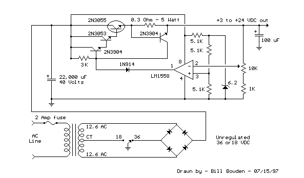
Variable 3 - 24 Volt / 3 Amp Power Supply circuit
This regulated power supply can be adjusted from 3 to 25 volts and is current limited to 2 amps as shown, but may be increased to 3 amps or more by selecting a smaller current sense resistor (0.3 ohm). The...
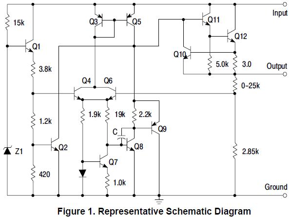
MC78L15ABPG Original supply
MC78L15ABPG positive voltage regulator, 100mA, TO-92
The MC78L15ABPG is a low-dropout (LDO) voltage regulator designed to provide a stable output voltage of 15V with a maximum output current of 100mA. This device is packaged in a TO-92 form factor, which is...
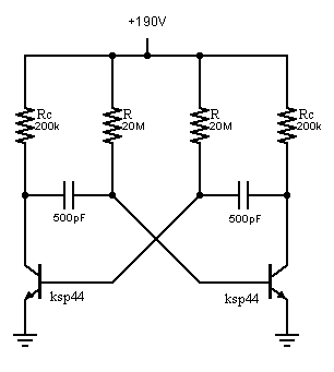
High voltage astable multivibrator problem
An oscillator is being developed to operate within the 200V range, targeting a frequency of approximately 1 kHz while minimizing current consumption. Initial testing has commenced.
The design of a high-voltage oscillator capable of operating at 200V and generating a frequency...
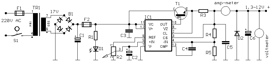
Small Variable power Supply
This is a simple yet reliable device based on one of the oldest integrated voltage regulators, the LM723.
The LM723 is a versatile voltage regulator that can be configured to provide a wide range of output voltages. It is capable of...
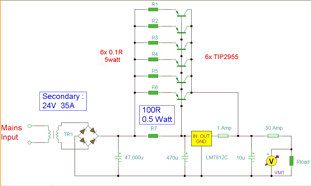
12 Volt 30 Amp PSU
Using a single 7812 IC voltage regulator and multiple outboard pass transistors, this power supply can deliver output load currents of up to 30 amps. The input transformer is likely to be the most expensive part of the entire project....
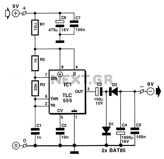
DC to DC converter electronic schematic
Individuals who frequently utilize battery-operated devices or require a negative voltage from a single positive source will find the following converter beneficial. This circuit can convert a 9 V positive battery voltage to a negative voltage using the well-known integrated...
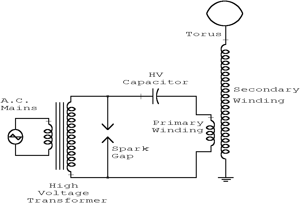
Tesla Coil
This webpage is designed to provide assistance and information for individuals interested in constructing a Tesla coil. It is recommended to utilize the additional resources available on this page. The electrical line voltage standard in the United States is 120V...
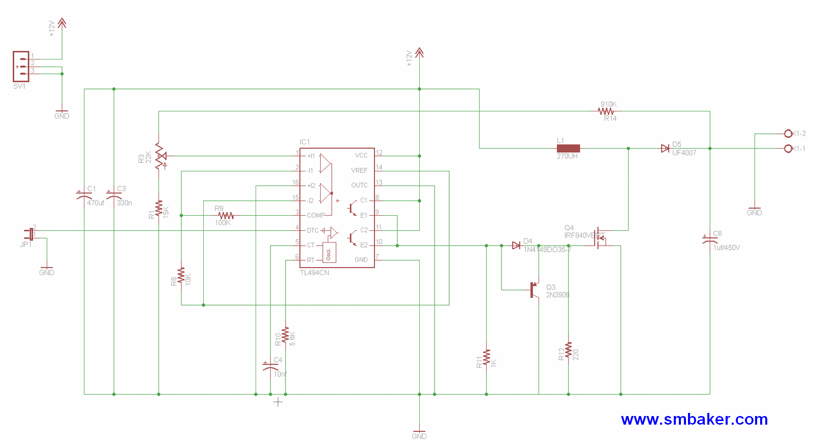
High voltage power supply
The design is based on the TubeHobby and serves as the power supply used in their NC2. This kit was constructed as an initial project involving nixie tubes, and a review of this excellent kit can be found in the...
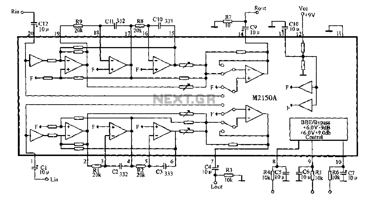
BBE monolithic integrated circuit M2150A
4V flat monitor high voltage power supply circuit diagram. A wide range of 7 to 40V to 5V DC-DC step-down circuit diagram. Light control switch circuit diagram for safety. Circuit 555 constitutes a control circuit diagram for photoelectric applications.
The 4V...