


3-30 V/2.5 A Stabilized variable power supply
#variable power supply
#stabilized
#2.5A
#3-30V
#short-circuit protection
#overload protection
#versatile
#electronics workshop
#voltage regulator
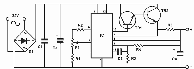
Description: This is a very useful project for anyone working in electronics. It is a versatile power supply that will solve most of the supply problems arising in the everyday work of any electronics workshop. It covers a wide range of voltages being continuously variable from 30 V down to 3 V. The output current is 2.5 A maximum, more than enough for most applications. The circuit is completely stabilized even at the extremes of its output range and is fully protected against short-circuits and overloading. More: Technical Specifications - Characteristics Input voltage: 24V DC Output current: 2.5 A Output voltage: 3-30V DC
How it Works The power supply is using a well-known and quite popular VOLTAGE STABILIZER IC the LM 723. The IC can be adjusted for output voltages that vary continuously between 2 and 37 VDC and has a current rating of 150 mA which is of course too low for any serious use. In order to increase the current handling capacity of the circuit, the output of the IC is used to drive a Darlington pair formed by two power transistors the BD 135 and the 2N 3055. The use of the transistors to increase the maximum current output limits the range of output voltages somewhat and this is why the circuit has been designed to operate from 3 to 30 VDC. The resistor R5 that you see connected in series with the output of the supply is used for the protection of the circuit from overloading. If an excessively large current flows through R5, the voltage across it increases and any voltage greater than 0.3 V across it has as a result to cut the supply off, thus effectively protecting it from overloads. This protection feature is built into the LM 723 and the voltage drop across R5 is sensed by the IC itself between pins 2 and 3. At the same time the IC is continuously comparing the output voltage to its internal reference and if the difference exceeds the designer's standards it corrects it automatically. This ensures great stability under different loads. The potentiometer P1 is used to adjust the output voltage at the desired level. If the full range from 3 to 30 V is desired then you should use a mains transformer with a secondary winding having a rating of at least 24 V/3 A. If the maximum voltage output is not desired, you can of course use a transformer with a lower secondary voltage output. (However, once rectified the voltage across the capacitor C2 should exceed by 4-5 volts the maximum output expected from the circuit.
The power supply circuit described utilizes the LM 723 voltage regulator IC, which serves as the core component for voltage regulation. This IC is known for its reliability and versatility, allowing for adjustable output voltages between 2 V and 37 V. Given its limited current output capacity of 150 mA, the circuit employs a Darlington pair configuration using BD 135 and 2N 3055 transistors to enhance the output current capability to a maximum of 2.5 A. This arrangement not only boosts the current handling but also defines the operational voltage range from 3 V to 30 V.
The design includes an important safety feature through the inclusion of a series resistor, R5, which acts as a current sensing element. When excessive current is detected, the voltage across R5 rises above 0.3 V, triggering the LM 723 to cut off the output, thus preventing damage to the circuit. The IC continuously monitors the output voltage against its internal reference, ensuring that voltage fluctuations are corrected automatically, maintaining stability under varying load conditions.
For adjusting the output voltage, a potentiometer (P1) is integrated into the circuit, allowing users to set the desired voltage level easily. Additionally, the transformer used in the circuit must be capable of providing a secondary voltage of at least 24 V at 3 A to ensure adequate performance across the entire output range. The design also notes that the rectified voltage across the smoothing capacitor (C2) must exceed the maximum output voltage by a margin of 4-5 volts to ensure proper operation. This comprehensive approach to design and safety makes this power supply a valuable tool for electronics professionals and hobbyists alike.This is a very useful project for anyone working in electronics. It is a versatile power supply that will solve most of the supply problems arising in the everyday work of any electronics work shop. It covers a wide range of voltages being continuously variable from 30 V down to 3 V. The output current is 2.5 A maximum, more than enough for most applications. The circuit is completely stabilised even at the extremes of its output range and is fully protected against short-circuits and overloading.
Technical Specifications - Characteristics Input voltage: 24V DC Output current: 2.5 A Output volytage: 3-30V DC -------------------------------------------------------------------------------- How it Works The power supply is using a well known and quite popular VOLTAGE STABILIZER IC the LM 723. The IC can be adjusted for out put voltages that vary continuously between 2 and 37 VDC and has a current rating of 150 mA which is of course too low for any serious use.
In order to increase the current handling capacity of the circuit the output of the IC is used to drive a darlington pair formed by two power transistors the BD 135 and the 2N 3055. The use of the transistors to increase the maximum current output limits the range of output voltages somewhat and this is why the circuit has been designed to operate from 3 to 30 VDC.
The resistor R5 that you see connected in series with the output of the supply is used for the protection of the circuit from overloading. If an excessively large current flows through R5, the voltage across it increases and any voltage greater than 0.3 V across it has as a result to cut the supply off, thus effectively protecting it from overloads.
This protection feature is built in the LM 723 and the voltage drop across R5 is sensed by the IC itself between pins 2 and 3. At the same time the IC is continuously comparing the output voltage to its internal reference and if the difference exceeds the designer?s standards it corrects it automatically.
This ensures great stability under different loads. The potentiometer P1 is used to adjust the out put voltage at the desired level. If the full range from 3 to 30 V is desired then you should use a mains transformer with a secondary winding having a rating of at least 24 V/3 A. If the maxi mum voltage output is not desired you can of course use a transformer with a lower secondary voltage output.
(However, once rectified the voltage across the capacitor C2 should exceed by 4-5 volts the maximum output expected from the circuit.
How it Works The power supply is using a well-known and quite popular VOLTAGE STABILIZER IC the LM 723. The IC can be adjusted for output voltages that vary continuously between 2 and 37 VDC and has a current rating of 150 mA which is of course too low for any serious use. In order to increase the current handling capacity of the circuit, the output of the IC is used to drive a Darlington pair formed by two power transistors the BD 135 and the 2N 3055. The use of the transistors to increase the maximum current output limits the range of output voltages somewhat and this is why the circuit has been designed to operate from 3 to 30 VDC. The resistor R5 that you see connected in series with the output of the supply is used for the protection of the circuit from overloading. If an excessively large current flows through R5, the voltage across it increases and any voltage greater than 0.3 V across it has as a result to cut the supply off, thus effectively protecting it from overloads. This protection feature is built into the LM 723 and the voltage drop across R5 is sensed by the IC itself between pins 2 and 3. At the same time the IC is continuously comparing the output voltage to its internal reference and if the difference exceeds the designer's standards it corrects it automatically. This ensures great stability under different loads. The potentiometer P1 is used to adjust the output voltage at the desired level. If the full range from 3 to 30 V is desired then you should use a mains transformer with a secondary winding having a rating of at least 24 V/3 A. If the maximum voltage output is not desired, you can of course use a transformer with a lower secondary voltage output. (However, once rectified the voltage across the capacitor C2 should exceed by 4-5 volts the maximum output expected from the circuit.
The power supply circuit described utilizes the LM 723 voltage regulator IC, which serves as the core component for voltage regulation. This IC is known for its reliability and versatility, allowing for adjustable output voltages between 2 V and 37 V. Given its limited current output capacity of 150 mA, the circuit employs a Darlington pair configuration using BD 135 and 2N 3055 transistors to enhance the output current capability to a maximum of 2.5 A. This arrangement not only boosts the current handling but also defines the operational voltage range from 3 V to 30 V.
The design includes an important safety feature through the inclusion of a series resistor, R5, which acts as a current sensing element. When excessive current is detected, the voltage across R5 rises above 0.3 V, triggering the LM 723 to cut off the output, thus preventing damage to the circuit. The IC continuously monitors the output voltage against its internal reference, ensuring that voltage fluctuations are corrected automatically, maintaining stability under varying load conditions.
For adjusting the output voltage, a potentiometer (P1) is integrated into the circuit, allowing users to set the desired voltage level easily. Additionally, the transformer used in the circuit must be capable of providing a secondary voltage of at least 24 V at 3 A to ensure adequate performance across the entire output range. The design also notes that the rectified voltage across the smoothing capacitor (C2) must exceed the maximum output voltage by a margin of 4-5 volts to ensure proper operation. This comprehensive approach to design and safety makes this power supply a valuable tool for electronics professionals and hobbyists alike.This is a very useful project for anyone working in electronics. It is a versatile power supply that will solve most of the supply problems arising in the everyday work of any electronics work shop. It covers a wide range of voltages being continuously variable from 30 V down to 3 V. The output current is 2.5 A maximum, more than enough for most applications. The circuit is completely stabilised even at the extremes of its output range and is fully protected against short-circuits and overloading.
Technical Specifications - Characteristics Input voltage: 24V DC Output current: 2.5 A Output volytage: 3-30V DC -------------------------------------------------------------------------------- How it Works The power supply is using a well known and quite popular VOLTAGE STABILIZER IC the LM 723. The IC can be adjusted for out put voltages that vary continuously between 2 and 37 VDC and has a current rating of 150 mA which is of course too low for any serious use.
In order to increase the current handling capacity of the circuit the output of the IC is used to drive a darlington pair formed by two power transistors the BD 135 and the 2N 3055. The use of the transistors to increase the maximum current output limits the range of output voltages somewhat and this is why the circuit has been designed to operate from 3 to 30 VDC.
The resistor R5 that you see connected in series with the output of the supply is used for the protection of the circuit from overloading. If an excessively large current flows through R5, the voltage across it increases and any voltage greater than 0.3 V across it has as a result to cut the supply off, thus effectively protecting it from overloads.
This protection feature is built in the LM 723 and the voltage drop across R5 is sensed by the IC itself between pins 2 and 3. At the same time the IC is continuously comparing the output voltage to its internal reference and if the difference exceeds the designer?s standards it corrects it automatically.
This ensures great stability under different loads. The potentiometer P1 is used to adjust the out put voltage at the desired level. If the full range from 3 to 30 V is desired then you should use a mains transformer with a secondary winding having a rating of at least 24 V/3 A. If the maxi mum voltage output is not desired you can of course use a transformer with a lower secondary voltage output.
(However, once rectified the voltage across the capacitor C2 should exceed by 4-5 volts the maximum output expected from the circuit.
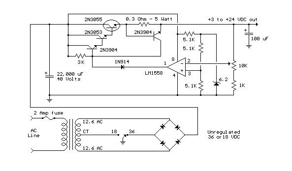
3V to 24V Variable Power Supply
This variable-regulated power supply operates within a voltage range of 3V to 24V, allowing adjustment from 3V to 25V. It is current limited to 2 amps, with the possibility of increasing the limit to 3 amps.
The described power supply features...
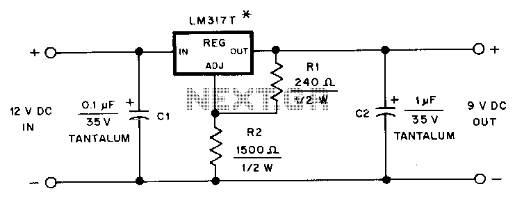
Hand-held-transceiver-dc-adapter
This adapter provides a regulated 9-V source for operating a Kenwood TR-2500 hand-held transceiver in a vehicle. The mounting tab of the LM317T is electrically connected to its output pin, which should be considered during the construction of the adapter....
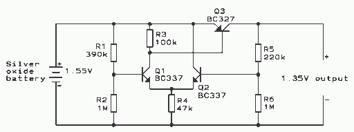
Voltage Regulator
This regulator is suitable for devices that need up to 1mA. For higher output current, the resistors would have to be scaled down in reverse proportion to the peak current expected. With the resistor values shown, the regulator draws a...
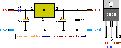
9 Volt 2 Ampere DC Power SupplyCircuit
A simple 9 Volt, 2 amp power supply utilizing a single integrated circuit (IC) regulator. This circuit is straightforward, as the regulator handles the majority of the work. The component used is the 7809 voltage regulator.
The circuit consists primarily of...
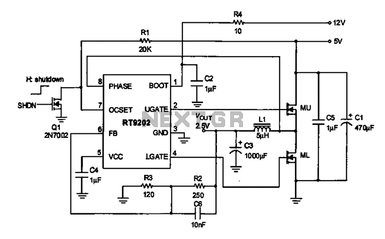
2.5V voltage regulator circuit
A 2.5V voltage regulator circuit is illustrated, which is part of a computer's motherboard. The circuit employs an oscillation circuit with the RT9202 control core chip, converting a 5V input supply into a regulated +2.5V output voltage, with the chip's...
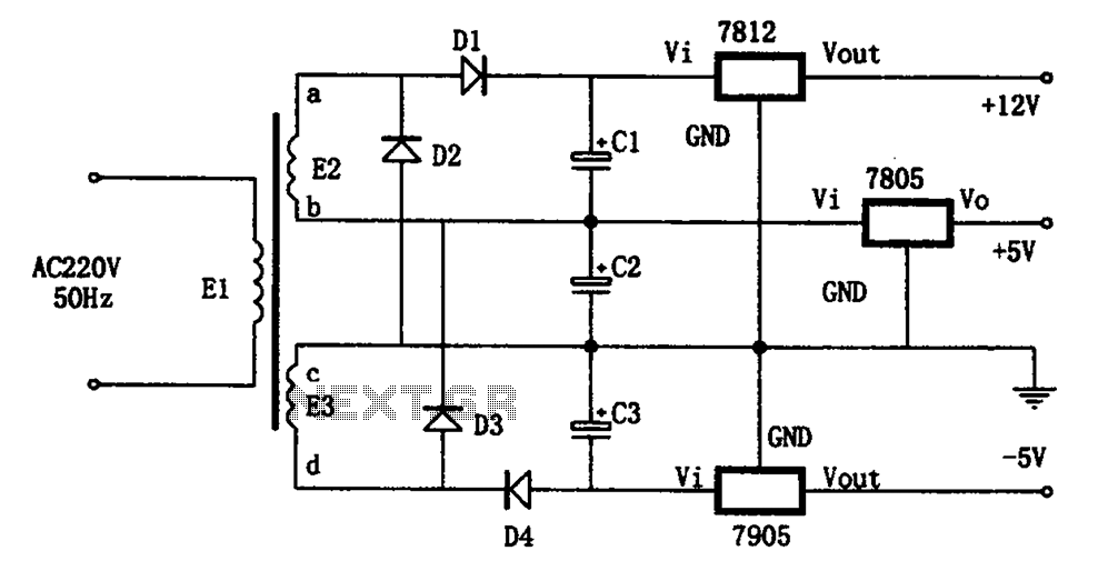
Special power circuits 7905 7805 7812
The circuit illustrated in the figure represents a specialized power supply configuration. It is straightforward in design and can be constructed using two identical secondary windings to generate three distinct DC voltage outputs: +5V, -5V, and +12V. The circuit features...
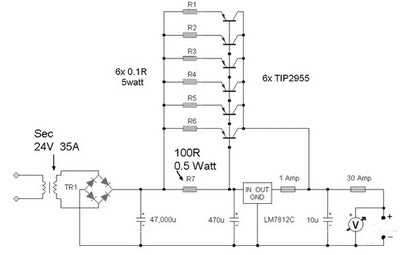
35 Ampere Power Supply
A 12 Volt 35 Amp power supply can be constructed using the LM7812 voltage regulator to provide a stable 12 Volt DC output. The power supply employs TIP2955 transistors as the main power regulators, with a configuration that utilizes six...
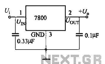
Three-terminal voltage regulator integrated fixed a typical wiring circuit
A fixed three-terminal integrated voltage regulator can be directly employed in various electronic devices as a voltage regulator. It features internal protections such as overcurrent protection, thermal protection, and safe operating area protection, making the circuit easy to use, safe,...
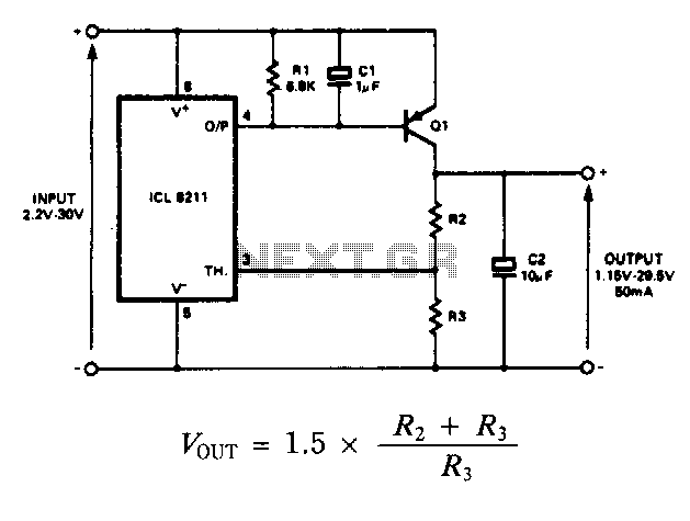
Positive-regulator-with-pnp-boost
The IC8211 serves as the voltage reference and regulator amplifier, with Q1 functioning as the series pass transistor. Resistor R1 defines the output current of the IC8211, while capacitors C1 and C2 ensure loop stability and help suppress the feedthrough...