


3-30V-universal-power-supply-module
#LM317
#adjustable regulator
#voltage regulation
#current limiting
#full-wave bridge rectifier
#filtering
#transformer
#power supply module
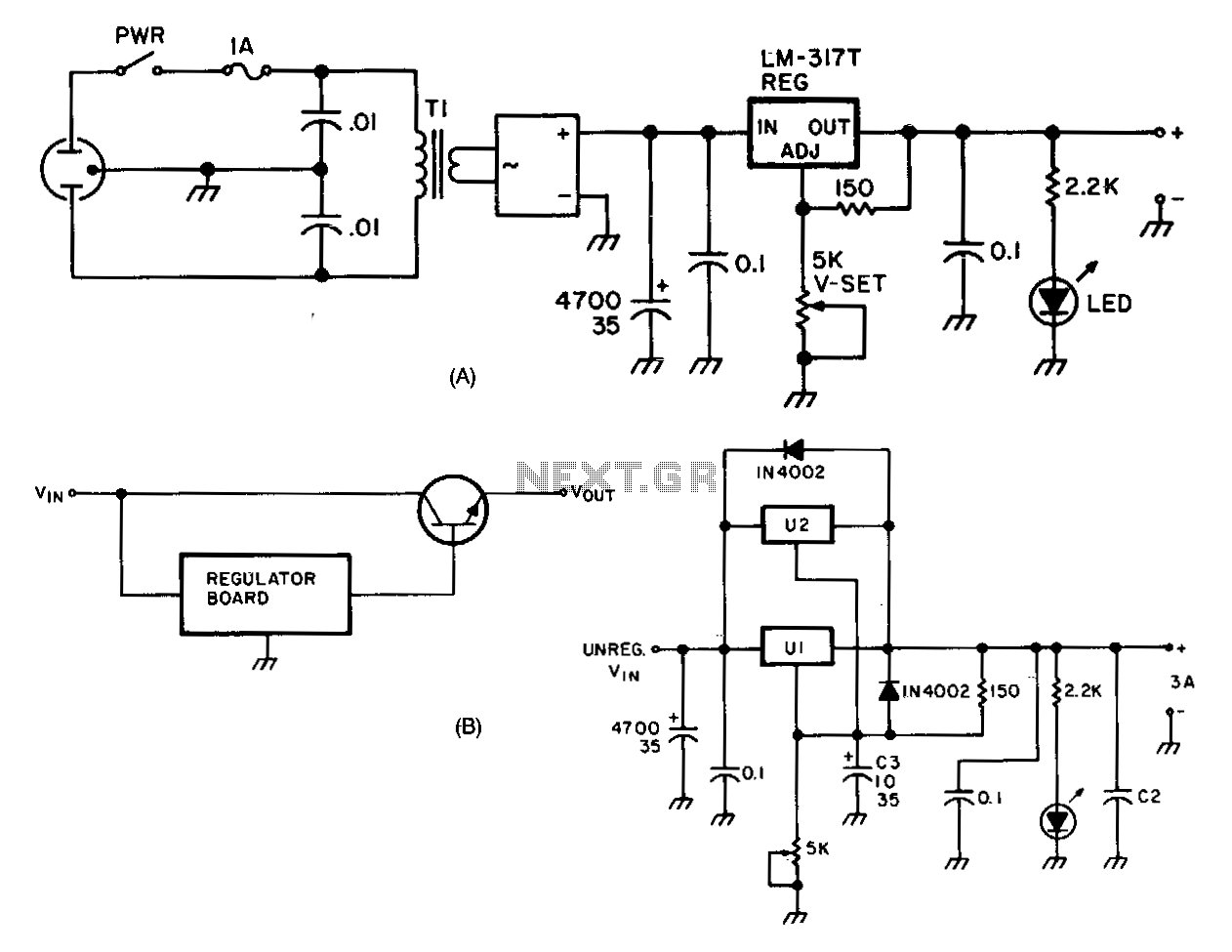
Description: The LM317 adjustable regulator (U1) offers short-circuit protection and automatic current limiting at 1.5 A. The input voltage to the regulator is provided by a 4-A 100 PIV full-wave bridge rectifier (DB1). Capacitor C1 serves as the initial filtering component. U1 additionally provides electronic filtering as part of its regulating function. The output voltage of the regulator is adjusted using a trim-potentiometer (R1). Bypass capacitors on both the input and output of U1 help prevent high-frequency oscillation. The transformer used must have a current rating of at least 1.8 times the rated continuous-duty output of the supply. Therefore, for a 1.5-A supply, a transformer rated at 2.7 A is recommended. For lighter or intermittent loads, a smaller 2.0-A transformer may be adequate. Connecting a second LM317 (U2) in parallel with U1 is an effective method to increase the current limiting threshold to 3 A while maintaining short-circuit protection. If a current exceeding 3 A is necessary, the regulator module can be utilized to control the base of one or more pass transistors.
The LM317 adjustable voltage regulator circuit is designed to provide a stable output voltage with built-in protections against overcurrent and short circuits. The configuration begins with the input voltage being rectified by the bridge rectifier (DB1), which converts AC voltage to DC. The 4-A, 100 PIV rating ensures that the rectifier can handle the required current and voltage without failure.
Capacitor C1 plays a critical role in smoothing the rectified voltage, reducing ripple and ensuring a more stable input for the LM317. The LM317 (U1) is then tasked with regulating the voltage output, which can be adjusted using the trim-potentiometer (R1). This adjustability makes the circuit versatile for various applications requiring different output voltages.
Bypass capacitors located at both the input and output of U1 are essential for filtering out high-frequency noise that could lead to instability in the output voltage, ensuring that the regulator operates effectively under varying load conditions.
The transformer must be properly rated to handle the load. The recommendation of a transformer rated at 2.7 A for a 1.5-A output ensures that the transformer can operate within safe limits, providing headroom for transient loads. For lighter applications, a 2.0-A transformer suffices, reducing cost and size.
In applications requiring higher current, the addition of a second LM317 (U2) in parallel with U1 effectively doubles the current capacity to 3 A. This method retains the protective features of the LM317, as both regulators share the load equally. For scenarios demanding even higher currents, the circuit can be expanded further by using the LM317 to drive external pass transistors, which can handle larger current loads while still being regulated by the LM317, maintaining the desired output characteristics.
This design exemplifies a robust and flexible power supply solution suitable for various electronic applications requiring adjustable output voltage and current limiting features.Ul, an LM317 adjustable regulator provides short-circuit protection and automatic current limiting at 1.5 A. The input voltage to the regulator is supplied by DBl, a 4-A 100 PIV full-wave bridge rectifier. Capacitor Cl provides initial filtering. Ul provides additional electronic filtering as part of the regulating function. The output level of the regulator is set by trim-pot Rl. Bypass capacitors on the input and output of Ul prevent high-frequency oscillation. The current rating of the transformer must be at least 1.8 times the rated continuous-duty output of the supply.
This means that a 1.5-A supply should use a 2. 7-A transformer. For light or intermittent loads, a smaller 2.0-A transformer should suffice. Wiring a second LM317, U2, in parallel with Ul is a quick and clean way to increase the currentlimiting threshold to 3 A withoutsacrificing short-circuit protection. When more than 3 A is required, the regulator module can be used to drive the base of one or more pass-transistors (see Fig.
75-2B).
The LM317 adjustable voltage regulator circuit is designed to provide a stable output voltage with built-in protections against overcurrent and short circuits. The configuration begins with the input voltage being rectified by the bridge rectifier (DB1), which converts AC voltage to DC. The 4-A, 100 PIV rating ensures that the rectifier can handle the required current and voltage without failure.
Capacitor C1 plays a critical role in smoothing the rectified voltage, reducing ripple and ensuring a more stable input for the LM317. The LM317 (U1) is then tasked with regulating the voltage output, which can be adjusted using the trim-potentiometer (R1). This adjustability makes the circuit versatile for various applications requiring different output voltages.
Bypass capacitors located at both the input and output of U1 are essential for filtering out high-frequency noise that could lead to instability in the output voltage, ensuring that the regulator operates effectively under varying load conditions.
The transformer must be properly rated to handle the load. The recommendation of a transformer rated at 2.7 A for a 1.5-A output ensures that the transformer can operate within safe limits, providing headroom for transient loads. For lighter applications, a 2.0-A transformer suffices, reducing cost and size.
In applications requiring higher current, the addition of a second LM317 (U2) in parallel with U1 effectively doubles the current capacity to 3 A. This method retains the protective features of the LM317, as both regulators share the load equally. For scenarios demanding even higher currents, the circuit can be expanded further by using the LM317 to drive external pass transistors, which can handle larger current loads while still being regulated by the LM317, maintaining the desired output characteristics.
This design exemplifies a robust and flexible power supply solution suitable for various electronic applications requiring adjustable output voltage and current limiting features.Ul, an LM317 adjustable regulator provides short-circuit protection and automatic current limiting at 1.5 A. The input voltage to the regulator is supplied by DBl, a 4-A 100 PIV full-wave bridge rectifier. Capacitor Cl provides initial filtering. Ul provides additional electronic filtering as part of the regulating function. The output level of the regulator is set by trim-pot Rl. Bypass capacitors on the input and output of Ul prevent high-frequency oscillation. The current rating of the transformer must be at least 1.8 times the rated continuous-duty output of the supply.
This means that a 1.5-A supply should use a 2. 7-A transformer. For light or intermittent loads, a smaller 2.0-A transformer should suffice. Wiring a second LM317, U2, in parallel with Ul is a quick and clean way to increase the currentlimiting threshold to 3 A withoutsacrificing short-circuit protection. When more than 3 A is required, the regulator module can be used to drive the base of one or more pass-transistors (see Fig.
75-2B).
Lithium Battery Charger Circuit With LM317 IC
This circuit illustrates a Lithium Battery Charger circuit diagram. Charging is achieved using a constant current of 60 mA for AA cells until a cutoff voltage of 2.4V per cell is reached, at which point the charging process must be...
Voltage Regulators
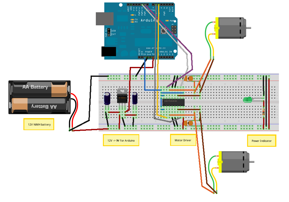
Until Willow Garage was acquired, there was work as a Web Robotics Engineer. This title reflects a role as a full-stack engineer focused on real-time, distributed robot control. Notable projects include an XML-RPC server and client for Node.js, a deprecated...
variable voltage and current power supply
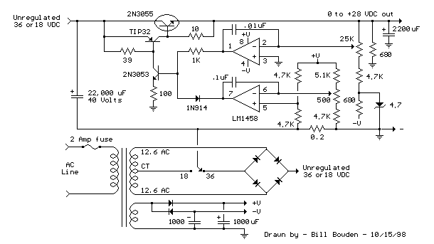
An alternative method for utilizing operational amplifiers (op-amps) to regulate a power supply is illustrated below. The power transformer necessitates an additional winding to provide the op-amps with a bipolar voltage of +/- 8 volts. This negative voltage is also...
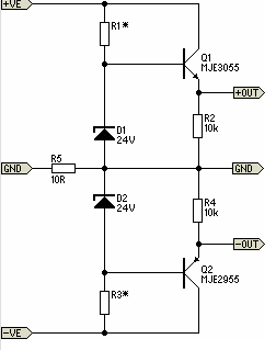
Simple Pre-Regulator
There will be many occasions when it is beneficial to utilize the P05 supply module sourced from a higher voltage supply. For instance, this could be advantageous when integrating balanced inputs.
The P05 supply module is designed to facilitate the conversion...
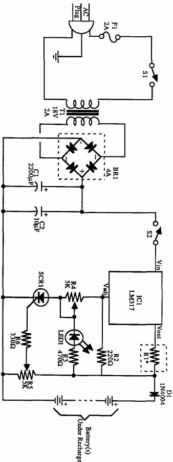
Build an Experimenters Power Supply
The incoming AC is routed to the primary terminals of a 12.6-volt transformer. The hot side of the AC is connected through a fuse and a single-pole single-throw (SPST) toggle switch. When the switch is in the OFF position, the...

transformer circuit
A static device that couples two circuits to transfer alternating current (AC) from one circuit to another through electromagnetic induction. The current maintains the same frequency but may vary in voltage, phase, or impedance values. A transformer consists of two...
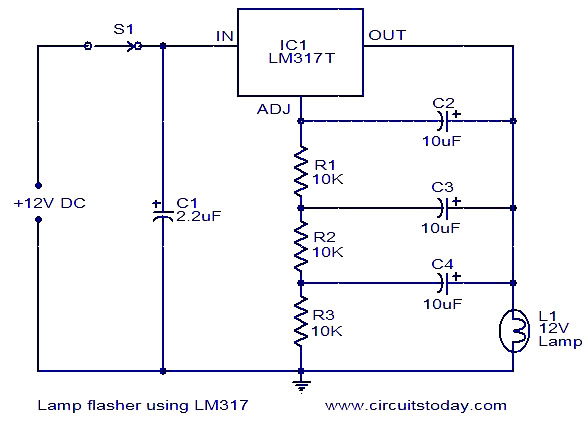
Lamp flasher using LM317
This document describes a lamp flasher circuit utilizing the adjustable voltage regulator IC LM317T. The LM317 can supply a maximum current of 1A, making it suitable for use with lamps up to 12W. This type of circuit has significant applications...

DIY Circuit Car Battery Charger
This simple circuit consists of a transformer, two diodes, a capacitor, and an ammeter. To charge a battery, connect the positive and negative terminals of the circuit to the corresponding terminals of the battery. When the battery is not charged,...
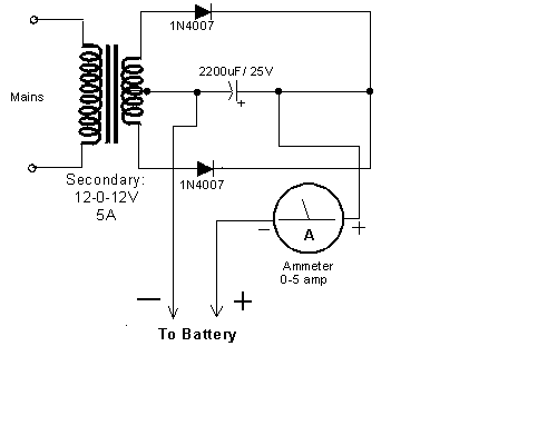
The Simplest Car Battery Charger
This very simple circuit uses a transformer, two diodes, a capacitor, and an ammeter. To charge a battery, just connect the + and - terminals of the circuit to the corresponding terminals of the battery. When the battery is not...