


50W-offline-switching-power-supply
#switching power supply
#flyback converter
#50W
#5V
#10A
#overcurrent protection
#primary side controller
#secondary side controller
#continuous mode
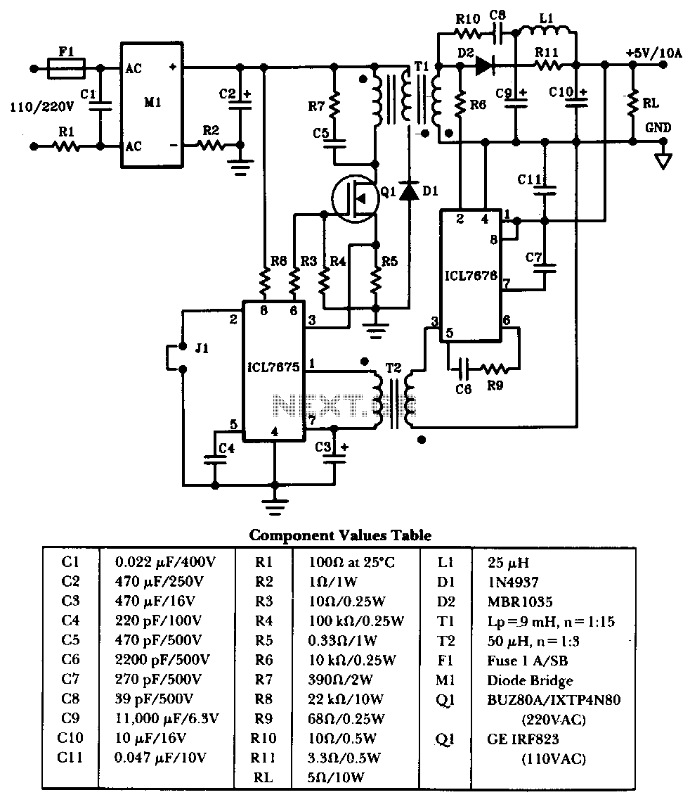
Description: The schematic illustrates a 50W power supply providing a 5V, 10A output. It operates as a flyback converter in continuous mode. The circuit incorporates both primary and secondary side controllers, offering full protection against fault conditions such as overcurrent. Once the fault condition is cleared, the power supply will initiate a soft-start cycle before returning to normal operation.
The power supply circuit utilizes a flyback topology, which is well-suited for applications requiring galvanic isolation and multiple output voltages. The continuous mode operation of the flyback converter ensures efficient energy transfer during the entire switching cycle, minimizing losses and enhancing performance.
The primary side controller is responsible for regulating the input voltage and managing the switching of the power transistor. This controller monitors the input conditions and adjusts the duty cycle to maintain the desired output voltage. The secondary side controller works in conjunction with the primary side to ensure the output voltage remains stable under varying load conditions.
Protection mechanisms are critical in this design. The overcurrent protection circuit is designed to detect excessive current flowing through the transformer. In the event of an overcurrent condition, the controller will immediately reduce the duty cycle or shut down the switching operation to prevent damage to the components. This feature enhances the reliability and longevity of the power supply.
The soft-start functionality is implemented to gradually ramp up the output voltage after a fault condition has been resolved. This process helps to avoid sudden inrush currents that could potentially damage connected loads or the power supply itself. The soft-start cycle typically involves slowly increasing the duty cycle of the power transistor, allowing the output voltage to rise smoothly to its nominal value.
Overall, this 50W power supply design is characterized by its robust protection features, efficient operation, and reliability, making it suitable for various applications where stable power is essential.The schematic shows a 50W power supply with a 5-V 10-A output. It is a flyback converter operating in the continuous mode. The circuit features a primary side and secondary side controller will full-protection from fault conditions such as overcurrent. After the fault condition has been removed, the power supply will enter the soft-start cycle before recommencing normal operation.
The power supply circuit utilizes a flyback topology, which is well-suited for applications requiring galvanic isolation and multiple output voltages. The continuous mode operation of the flyback converter ensures efficient energy transfer during the entire switching cycle, minimizing losses and enhancing performance.
The primary side controller is responsible for regulating the input voltage and managing the switching of the power transistor. This controller monitors the input conditions and adjusts the duty cycle to maintain the desired output voltage. The secondary side controller works in conjunction with the primary side to ensure the output voltage remains stable under varying load conditions.
Protection mechanisms are critical in this design. The overcurrent protection circuit is designed to detect excessive current flowing through the transformer. In the event of an overcurrent condition, the controller will immediately reduce the duty cycle or shut down the switching operation to prevent damage to the components. This feature enhances the reliability and longevity of the power supply.
The soft-start functionality is implemented to gradually ramp up the output voltage after a fault condition has been resolved. This process helps to avoid sudden inrush currents that could potentially damage connected loads or the power supply itself. The soft-start cycle typically involves slowly increasing the duty cycle of the power transistor, allowing the output voltage to rise smoothly to its nominal value.
Overall, this 50W power supply design is characterized by its robust protection features, efficient operation, and reliability, making it suitable for various applications where stable power is essential.The schematic shows a 50W power supply with a 5-V 10-A output. It is a flyback converter operating in the continuous mode. The circuit features a primary side and secondary side controller will full-protection from fault conditions such as overcurrent. After the fault condition has been removed, the power supply will enter the soft-start cycle before recommencing normal operation.
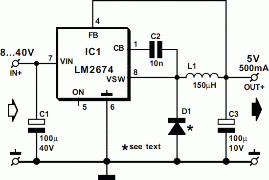
5V Switch-Mode Power Supply circuit
This 5-volt Switch Mode Power Supply circuit utilizes an integrated circuit (IC) from National Semiconductor, which specializes in the production and design of ICs for switch-mode power supply applications.
The 5-volt Switch Mode Power Supply (SMPS) circuit is designed to efficiently...
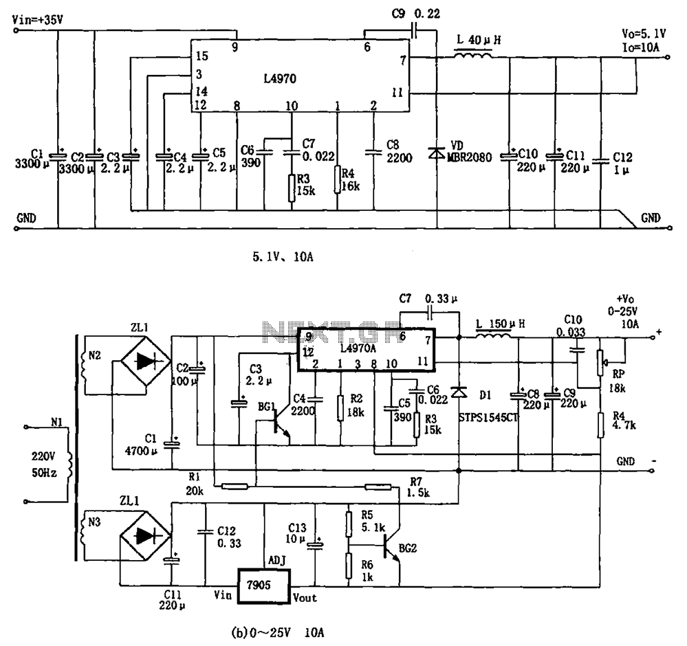
By the high-power switching power supply L4970A
The L4970A power switching supply is a high-power monolithic integrated switching regulator, packaged in a SIP-15 format. It has specific characteristics: (1) The input voltage must be at least 11V, typically ranging from 15V to 40V; (2) The output voltage...
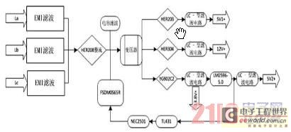
The anti exciting type switching power supply based on FSDM0565R is designed
Currently, the switching power supply boasts high performance with an efficiency of 75%. The efficiency of single-scale integration switching power supplies has exceeded 90%. This advancement addresses energy concerns and enhances the performance of numerous energy-saving electrical devices. The text...

60 Watt switching Power supply
This paper gives a practical example of the design of an off-line switching power supply. Factors governing the choice of a discontinuous flyback topology are discussed. The design uses a pulsed-width modulation (PWM) control scheme implemented with a Unitrode UC3840...
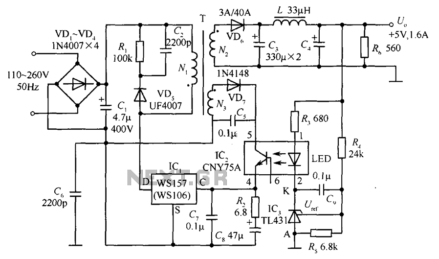
WSl57 + 5V 1.6A precision switching power supply circuit comprising
The circuit incorporates an optical coupler (CNY75A) and an adjustable precision shunt regulator (TL431). It includes current limiting resistors R3, R4, and R5 for the sampling resistor. As the output voltage (Uo) varies, the voltage across the sampling resistor and...

24VDC-220VDC vehicle carried switching power supply based on inverter circuit
With the increase in the variety of modern electrical equipment for vehicles and the rise in power levels, there is a growing demand for different types of power supplies, including AC and DC sources. The power system needs to utilize...

simple switching power supply 15 watt
The pulse transformer T1 utilizes a ferrite core, specifically M2500NMS-2 or M2000NM9, with dimensions of Sh5h5 (cross-section of the magnetic coils at 5G—5 mm with a center gap). The winding wire is of type PEL-2. The primary winding consists of...
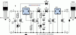
5V Power Supply For On Train Radio Camera
A radio camera on a model railway is designed to transmit continuously while the train is in motion and to continue transmitting for a few minutes after the train stops. If the train starts moving again after a relatively long...

Self oscillating flyback converter
Diode D1 prevents negative spikes from occurring at the MOSFET gate. The 100-ohm resistor acts as a parasitic suppressor, while Z1 functions as a dissipative voltage regulator for the output and clips the drain voltage to a level below the...