


555 circuit Can supply enough neg voltage
#555 timer
#negative voltage
#LM324
#AD736JN
#voltage supply
#circuit design
#operational amplifier
#power management
#electronics
#schematic
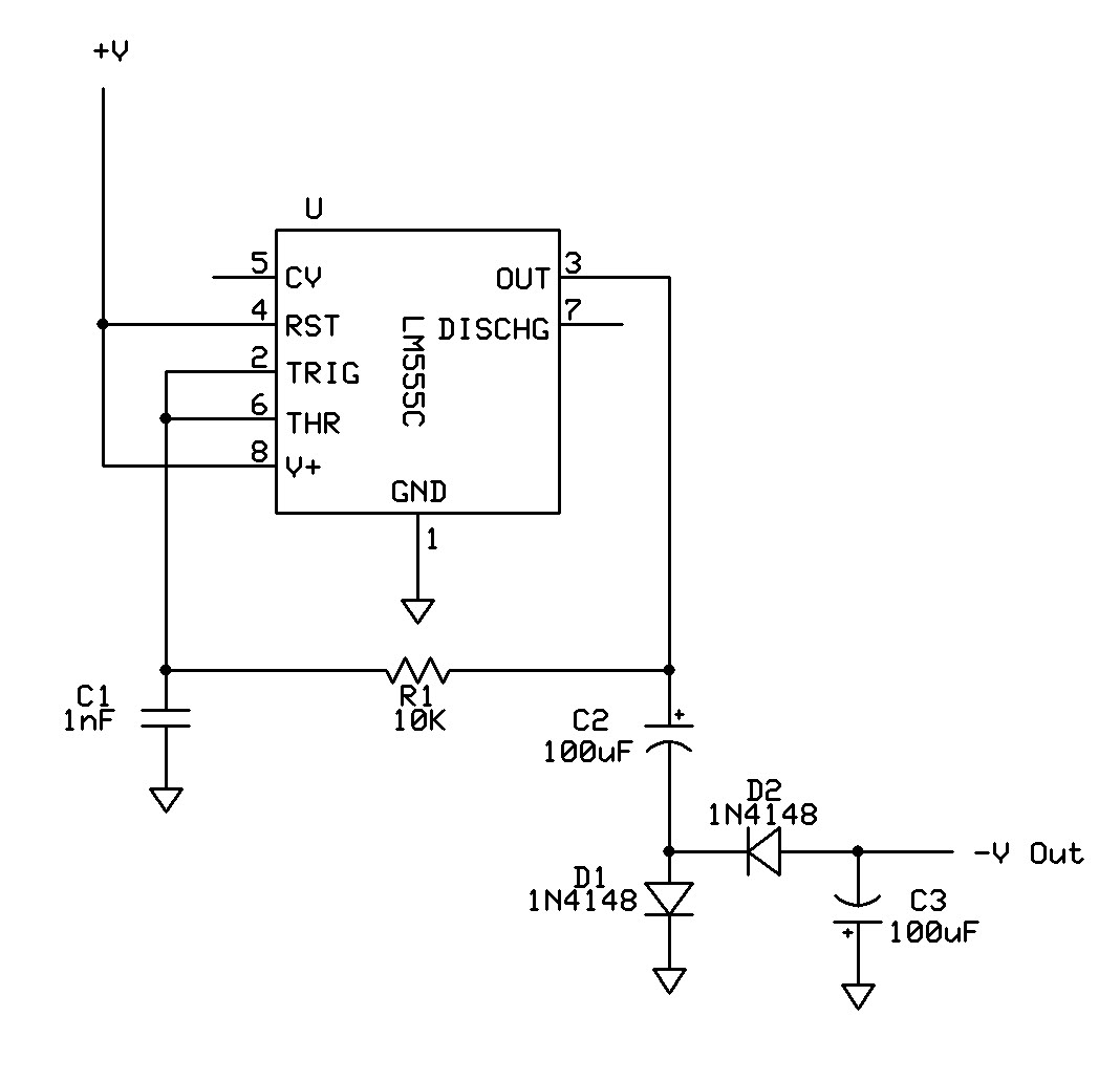
Description: Can a 555 negative supply circuit, like the one below I pulled from another schematic, supply enough negative voltage to an LM324 and an AD736JN?
The 555 timer integrated circuit can be configured to generate a negative voltage supply, which can be utilized to power operational amplifiers such as the LM324 and the AD736JN. The operation of the 555 timer in this configuration typically involves using external components such as resistors and capacitors to establish the desired output voltage level.
In a standard negative voltage supply circuit using a 555 timer, the circuit is configured in astable or monostable mode to generate a square wave output. This output can then be fed into a charge pump or a voltage inverter circuit, which converts the positive voltage into a negative voltage. The LM324, a quad operational amplifier, requires a negative supply voltage for operation in certain configurations, particularly when dealing with bipolar input signals. Similarly, the AD736JN, which is a precision analog multiplier, also benefits from a dual supply configuration for optimal performance.
When designing the circuit, it is essential to consider the output current requirements of the LM324 and AD736JN to ensure that the 555 timer can provide sufficient current without overheating or failing. The voltage levels should be monitored and adjusted as necessary to meet the specifications of the components being powered. Additionally, proper decoupling capacitors should be used to stabilize the supply voltage and minimize noise in the circuit.
In conclusion, a 555 timer configured as a negative supply circuit can indeed supply the necessary negative voltage for the LM324 and AD736JN, provided that the circuit is designed with attention to the load requirements and stability considerations.Can a 555 negative supply circuit, like the one below I pulled from another schematic, supply enough negative voltage to a LM324 and a AD736JN? I`m..
The 555 timer integrated circuit can be configured to generate a negative voltage supply, which can be utilized to power operational amplifiers such as the LM324 and the AD736JN. The operation of the 555 timer in this configuration typically involves using external components such as resistors and capacitors to establish the desired output voltage level.
In a standard negative voltage supply circuit using a 555 timer, the circuit is configured in astable or monostable mode to generate a square wave output. This output can then be fed into a charge pump or a voltage inverter circuit, which converts the positive voltage into a negative voltage. The LM324, a quad operational amplifier, requires a negative supply voltage for operation in certain configurations, particularly when dealing with bipolar input signals. Similarly, the AD736JN, which is a precision analog multiplier, also benefits from a dual supply configuration for optimal performance.
When designing the circuit, it is essential to consider the output current requirements of the LM324 and AD736JN to ensure that the 555 timer can provide sufficient current without overheating or failing. The voltage levels should be monitored and adjusted as necessary to meet the specifications of the components being powered. Additionally, proper decoupling capacitors should be used to stabilize the supply voltage and minimize noise in the circuit.
In conclusion, a 555 timer configured as a negative supply circuit can indeed supply the necessary negative voltage for the LM324 and AD736JN, provided that the circuit is designed with attention to the load requirements and stability considerations.Can a 555 negative supply circuit, like the one below I pulled from another schematic, supply enough negative voltage to a LM324 and a AD736JN? I`m..
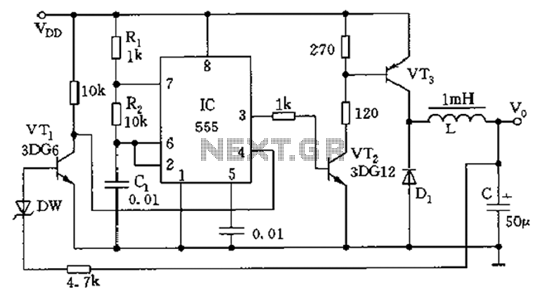
Inductive switching power supply circuit diagram
The circuit consists of a 555 timer configured as an astable multivibrator along with resistors R1 and R2 and capacitor C1. It generates an oscillation frequency of approximately 10 kHz with a duty cycle close to 50%. Transistors VT2 and...
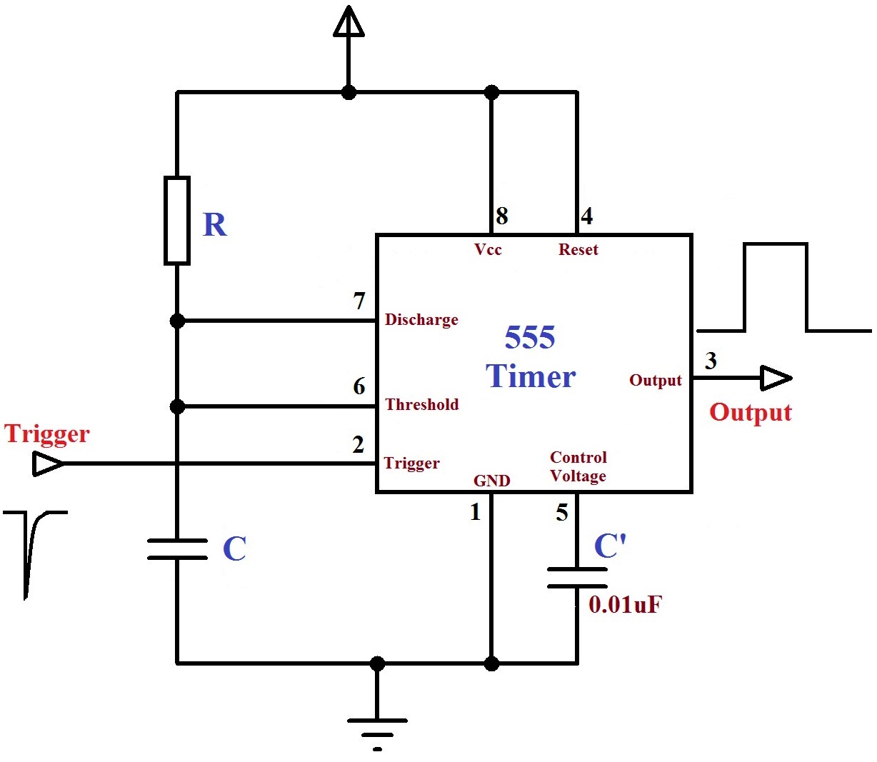
monostable multivibrator 555 timer
The monostable mode of the 555 Timer operates by having one stable state and switching to an unstable state for a predetermined time period T when triggered. The time period T is determined by the RC time constant in the...
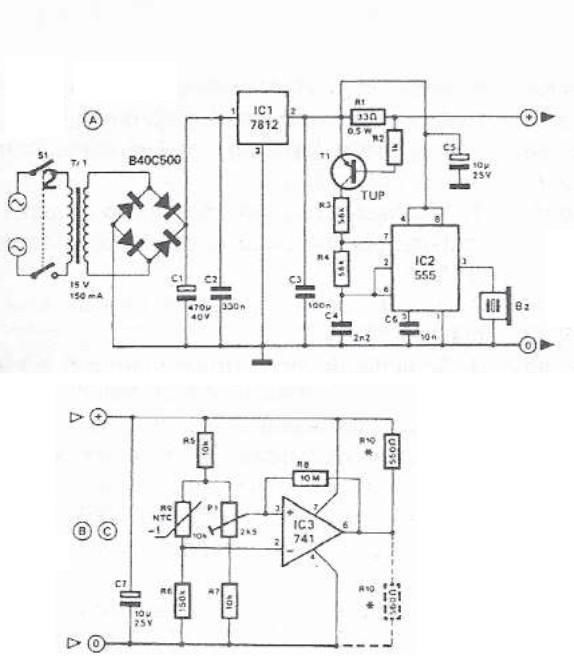
555 timer circuit temperature monitoring system
This 555 timer circuit temperature monitoring system project can monitor temperature at up to four points. The system allows for the selection of whether the alarm should be triggered when the temperature increases or decreases, depending on the resistance R10....
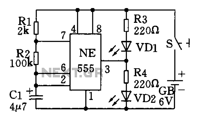
The use of low frequency oscillation base 555 circuit made flashing light circuit Circuit II
The circuit utilizes a 555 timer as the central component of a flashing light circuit. In normal operation, the light-emitting diodes (LEDs) VD1 and VD2 alternate flashing. The circuit comprises the NE555 timer, resistors R1 and R2, and capacitor C1,...
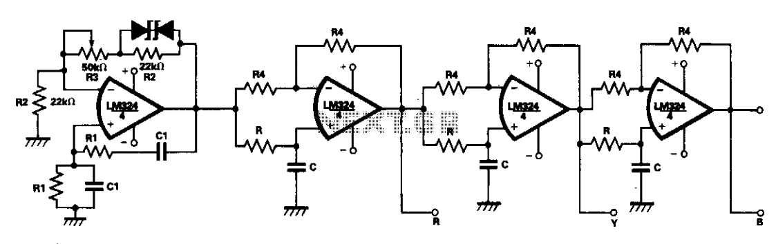
Phase tracking three-phase generator
A single LM324 chip can effectively reduce the size of a 3-phase waveform generator through the use of active R-C networks, making it advantageous for compact and stable 3-phase inverters. One quarter of the LM324 functions as a Wien bridge...
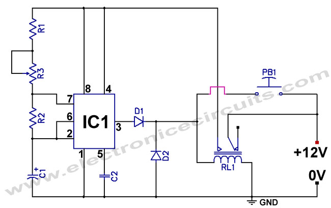
555 Low power Consumption Timer Circuit
The standard 555 timer circuit consumes power from the battery even when the start push-button (PB1) is not pressed, due to a potential divider created by three 5kΩ resistors within the integrated circuit (IC). This power consumption, referred to as...

On And Off Button
In this simple circuit, the chip receives more attention than usual. It is remarkable what can be constructed with a 555 timer. There is a persistent fascination with its capabilities.
The 555 timer IC is a versatile component widely used in...
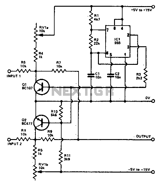
Beam sputter for oscilloscope
The foundation of the beam splitter utilizes a 555 timer configured as an astable multivibrator. Signals at the two inputs are alternately displayed on the oscilloscope, exhibiting a distinct separation between them. The output is regulated by the tandem potentiometer...
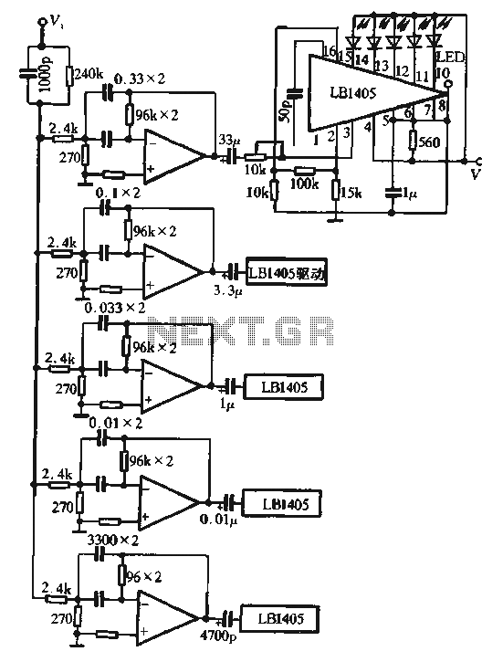
Five sections of the spectrum display circuit
The circuit utilizes the LM324 as a band-pass filter and the LB1405 as a driver for a five-band spectrum display. The selected frequency harmonics are centered at 100 Hz, 330 Hz, 1 kHz, 3.3 kHz, and 10 kHz. The band-pass...