


5V transformer less power supply
#transformerless
#5V
#rectifier
#Zener diode
#current limiting
#filter capacitor
#DC power
#mains voltage
#voltage regulation
#bridge rectifier
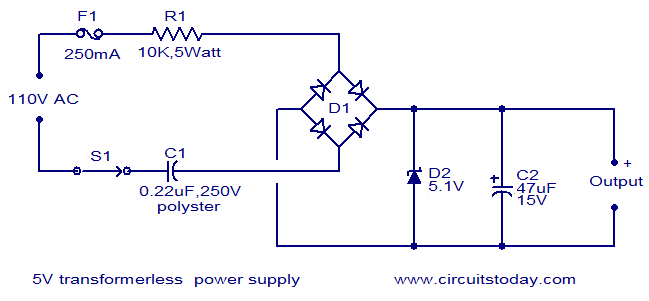
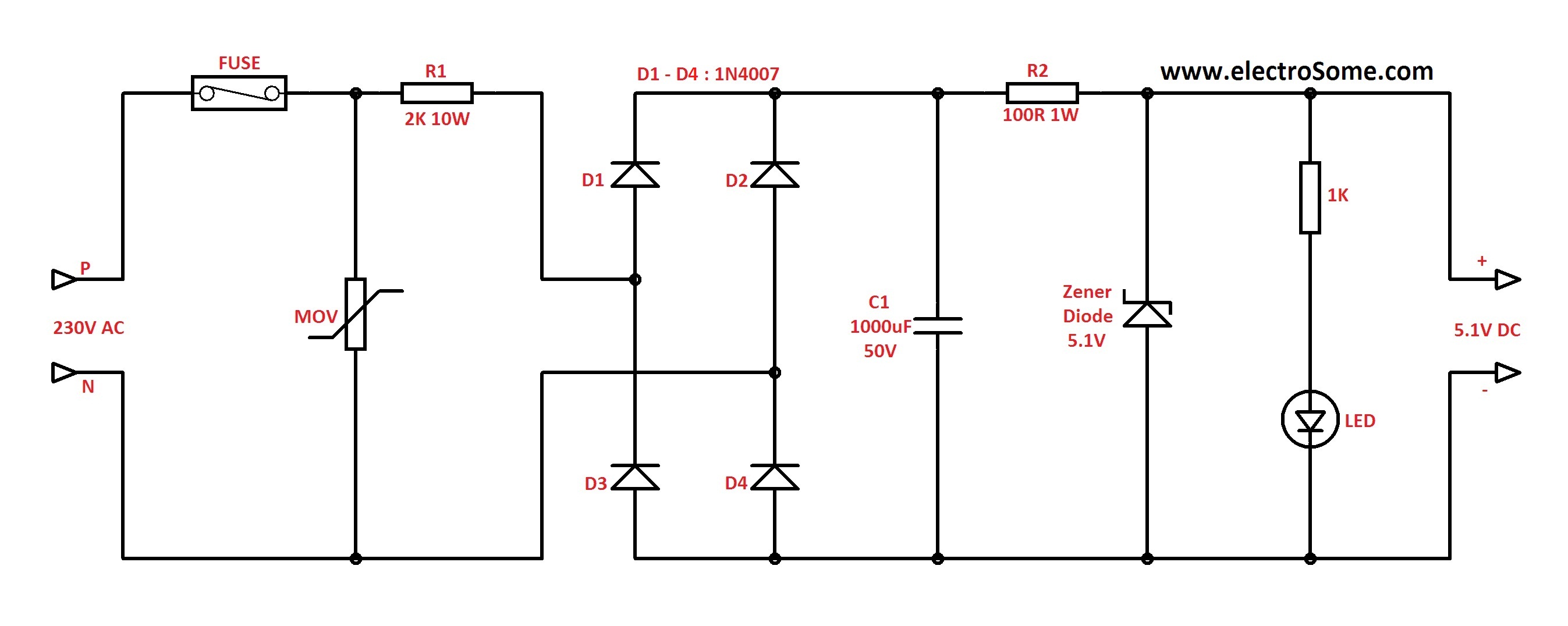
Description: The circuit diagram illustrates a 5V transformerless power supply utilizing minimal components. The operation of this circuit is straightforward. Resistor R1 serves as a current limiter, while bridge D1 rectifies the mains voltage. The Zener diode regulates the output from the rectifier to provide a stable 5V DC, and capacitor C2 functions as a filter.
This transformerless power supply circuit is designed for low-power applications where isolation from the mains voltage is not a primary concern. The key components include a resistor (R1), a bridge rectifier (D1), a Zener diode, and a filter capacitor (C2).
Resistor R1 limits the current flowing through the circuit, ensuring that the downstream components are not subjected to excessive current levels. The choice of resistance value is critical, as it must be calculated based on the expected load current and the input voltage to maintain safe operating conditions.
The bridge rectifier (D1) consists of four diodes arranged in a configuration that allows AC mains voltage to be converted into pulsating DC voltage. This rectification process is essential for powering DC loads. The output of the rectifier is characterized by a ripple voltage, which can be smoothed out by the filter capacitor (C2).
The Zener diode is employed to regulate the output voltage to a precise 5V DC. It operates in reverse breakdown mode, maintaining a constant voltage across its terminals as long as the current remains within specified limits. This regulation is crucial for applications requiring stable voltage levels.
Capacitor C2 plays a vital role in filtering the rectified output. It charges during the peak voltage periods and discharges during the lower voltage intervals, thus reducing the ripple voltage and providing a more stable DC output. The capacitance value must be selected based on the load requirements and the level of acceptable ripple.
Overall, this circuit provides a compact and efficient solution for converting AC mains voltage to a low-voltage DC supply, suitable for powering small electronic devices. However, it is essential to consider safety and compliance with electrical standards, particularly when working with mains voltage.Here is the circuit diagram of a 5V transformer less power supply using minimum components. The working of this circuit is quite simple. Resistor R1 does the job of current limiting and bridge D1 rectifies the mains voltage. The Zener diode regulates the rectifier output to obtain a steady 5V DC and capacitor C2 acts as a filter.
This transformerless power supply circuit is designed for low-power applications where isolation from the mains voltage is not a primary concern. The key components include a resistor (R1), a bridge rectifier (D1), a Zener diode, and a filter capacitor (C2).
Resistor R1 limits the current flowing through the circuit, ensuring that the downstream components are not subjected to excessive current levels. The choice of resistance value is critical, as it must be calculated based on the expected load current and the input voltage to maintain safe operating conditions.
The bridge rectifier (D1) consists of four diodes arranged in a configuration that allows AC mains voltage to be converted into pulsating DC voltage. This rectification process is essential for powering DC loads. The output of the rectifier is characterized by a ripple voltage, which can be smoothed out by the filter capacitor (C2).
The Zener diode is employed to regulate the output voltage to a precise 5V DC. It operates in reverse breakdown mode, maintaining a constant voltage across its terminals as long as the current remains within specified limits. This regulation is crucial for applications requiring stable voltage levels.
Capacitor C2 plays a vital role in filtering the rectified output. It charges during the peak voltage periods and discharges during the lower voltage intervals, thus reducing the ripple voltage and providing a more stable DC output. The capacitance value must be selected based on the load requirements and the level of acceptable ripple.
Overall, this circuit provides a compact and efficient solution for converting AC mains voltage to a low-voltage DC supply, suitable for powering small electronic devices. However, it is essential to consider safety and compliance with electrical standards, particularly when working with mains voltage.Here is the circuit diagram of a 5V transformer less power supply using minimum components. The working of this circuit is quite simple. Resistor R1 does the job of current limiting and bridge D1 rectifies the mains voltage. The Zener diode regulates the rectifier output to obtain a steady 5V DC and capacitor C2 acts as a filter.
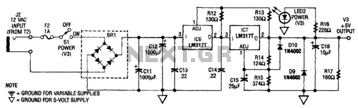
+5V Supply Circuit
The power supply presented is intended to function with a wall transformer. This circuit can be utilized alongside a variable supply for testing circuits in a laboratory setting. T2 serves as a 12-V wall transformer.
The power supply circuit is designed...
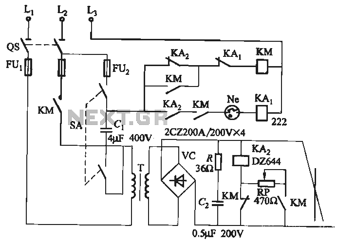
Single-phase rectifier DC welding power load from road circuit
A single-phase rectifier DC welding power load from the road circuit is presented. The contactor KM utilizes a CJ20-40A model rated for 220V. An adjustment potentiometer RP is employed to ensure proper arcing, while the relay KA2 is designed for...
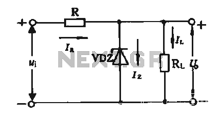
Regulator circuit silicon resistor formed
The simple voltage regulator circuit consists of a silicon regulator and a resistor. It is designed to rectify and filter DC voltage, as illustrated in the accompanying figure. The voltage regulator is connected in parallel with the load, and the...
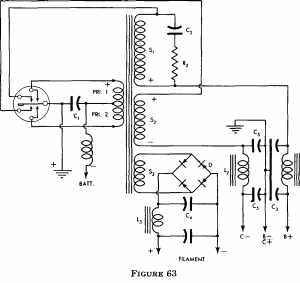
power supply design
The more one understands about any subject, the more interesting it becomes. As this article is read, it will be found that the subject of...
A comprehensive electronic schematic typically involves various components, each serving a specific function in the overall...
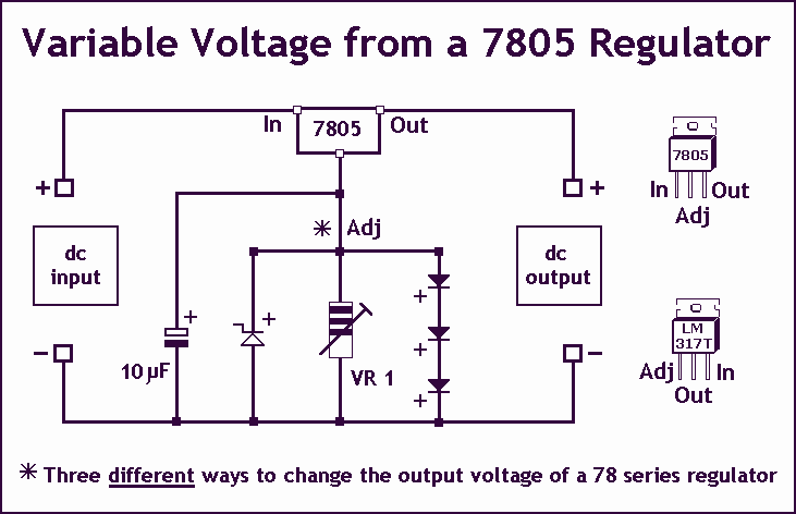
Variable Voltage Regulation
Controlling the output voltage from a regulator can be made variable in three ways:
1. Using a fixed reference zener diode to increase the output by the value of the zener
2. A variable resistor for variable output, note that...
transformerless low cost power supply
In Capacitor Power Supplies, a Voltage Dropping Capacitor is used in series with the phase line. Ordinary capacitors are unsuitable for these applications because mains spikes can create holes in the dielectric of standard capacitors, leading to failure. This failure...

psu
The Chameleon II Power Supply Circuits convert the raw input supply into stable voltage outputs necessary for the Chameleon interfaces. The outputs provided are +5V, +12V, and -12V.
The Chameleon II Power Supply Circuits are designed to ensure reliable operation of...
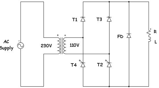
introduction to controlled rectifiers with converter
Controlled rectifiers are line-commutated AC to DC power converters that convert a fixed voltage and fixed frequency AC power supply into a variable DC output voltage. The input supply provided to a controlled rectifier is an AC supply with a...
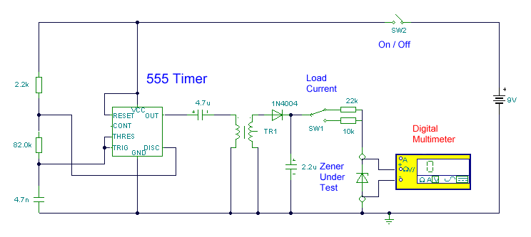
Zener Diode Tester Test Gears Circuits Schematics
This circuit utilizes a single 555 Timer IC along with a small transformer to generate high voltage for testing zener diodes with voltage ratings up to 50VDC. The 555 timer operates in astable mode, with the output from pin 3...