


A Simple Capacitance Multiplier Power Supply For Class-A Amplifiers
#capacitance multiplier
#Class-A amplifier
#low ripple
#regulated supply
#filter
#schematic
#electronics
#DIY
#audio
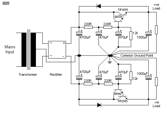
Description: Since I have provided the schematic for John L Linsley-Hood's Class-A amplifier, I felt that some readers may wish to experiment with the concept. Unfortunately, a very low ripple power supply is needed for all Class-A amps, and the most common solution is to use a regulated supply. A basic circuit is provided in the article, but it is assumed that the builder knows all the pitfalls. The supplied schematic is in fact for a capacitance multiplier filter (not a regulator), but is somewhat lacking and can be improved dramatically.
The Class-A amplifier is a type of electronic amplifier that conducts over the entire range of the input signal cycle, offering high fidelity and linearity. However, it requires a power supply that minimizes ripple voltage to ensure optimal performance. The use of a regulated power supply is essential for maintaining the stability and quality of the output signal.
A capacitance multiplier filter is often employed in this context to reduce ripple voltage. This circuit essentially uses a combination of resistors, capacitors, and transistors to increase the effective capacitance seen by the load, thereby smoothing out variations in the power supply voltage. The basic topology includes an input capacitor connected to the power supply, followed by a transistor configured to amplify the capacitance effect of a smaller capacitor connected to the output.
To enhance the performance of the capacitance multiplier, several improvements can be implemented. First, ensuring that the transistor used has a low output impedance can significantly reduce the output ripple. Additionally, selecting high-quality capacitors with low equivalent series resistance (ESR) will further diminish ripple effects. The layout of the circuit is also critical; minimizing the distance between the capacitors and the load can help reduce inductive effects which may introduce noise.
Furthermore, incorporating a feedback loop in the design can help regulate the output voltage more effectively, allowing for better performance across varying load conditions. This can be achieved by using an operational amplifier that monitors the output voltage and adjusts the base voltage of the transistor accordingly to maintain a constant output level.
Overall, while the provided schematic serves as a foundation, careful consideration of component selection, circuit layout, and additional features can significantly enhance the performance of the Class-A amplifier power supply.Since I have provided the schematic for John L Linsley-Hood`s Class-A amplifier, I felt that some readers may wish to experiment with the concept. Unfortunately, a very low ripple power supply is needed for all Class-A amps, and the most common solution is to use a regulated supply.
A basic circuit is provided in the article, but it is assumed that the builder knows all the pitfalls. The supplied schematic is in fact for a capacitance multiplier filter (not a regulator), but is somewhat lacking (I feel) and can be improved dramatically.
The Class-A amplifier is a type of electronic amplifier that conducts over the entire range of the input signal cycle, offering high fidelity and linearity. However, it requires a power supply that minimizes ripple voltage to ensure optimal performance. The use of a regulated power supply is essential for maintaining the stability and quality of the output signal.
A capacitance multiplier filter is often employed in this context to reduce ripple voltage. This circuit essentially uses a combination of resistors, capacitors, and transistors to increase the effective capacitance seen by the load, thereby smoothing out variations in the power supply voltage. The basic topology includes an input capacitor connected to the power supply, followed by a transistor configured to amplify the capacitance effect of a smaller capacitor connected to the output.
To enhance the performance of the capacitance multiplier, several improvements can be implemented. First, ensuring that the transistor used has a low output impedance can significantly reduce the output ripple. Additionally, selecting high-quality capacitors with low equivalent series resistance (ESR) will further diminish ripple effects. The layout of the circuit is also critical; minimizing the distance between the capacitors and the load can help reduce inductive effects which may introduce noise.
Furthermore, incorporating a feedback loop in the design can help regulate the output voltage more effectively, allowing for better performance across varying load conditions. This can be achieved by using an operational amplifier that monitors the output voltage and adjusts the base voltage of the transistor accordingly to maintain a constant output level.
Overall, while the provided schematic serves as a foundation, careful consideration of component selection, circuit layout, and additional features can significantly enhance the performance of the Class-A amplifier power supply.Since I have provided the schematic for John L Linsley-Hood`s Class-A amplifier, I felt that some readers may wish to experiment with the concept. Unfortunately, a very low ripple power supply is needed for all Class-A amps, and the most common solution is to use a regulated supply.
A basic circuit is provided in the article, but it is assumed that the builder knows all the pitfalls. The supplied schematic is in fact for a capacitance multiplier filter (not a regulator), but is somewhat lacking (I feel) and can be improved dramatically.
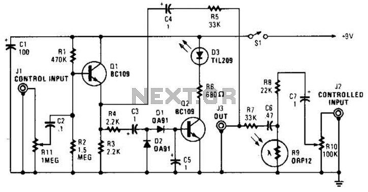
Automatic Fader Circuit
In this circuit, audio input to the control channel is amplified and rectified by diodes D1 and D2. This direct current level activates LED D3 through transistor Q2. The illumination from LED D3 causes R9, a light-dependent resistor, to reduce...

Audio Fader
In this circuit, Q1 serves as a simple amplifier with gain control provided by a variable emitter resistance supplied by FET Q2. When switch SI is in the up position, capacitor C3 discharges through resistor R5, resulting in a decrease...
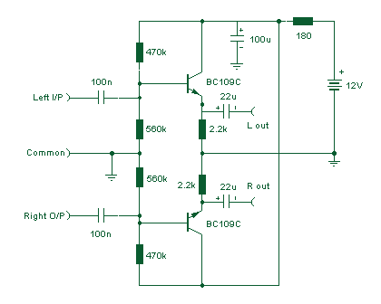
Audio Line Driver
The preamplifier described is engineered with a low output impedance, specifically designed to handle long cable runs. This feature allows for listening to a remote music source without the need for expensive screened cables. The preamplifier boasts a very low...
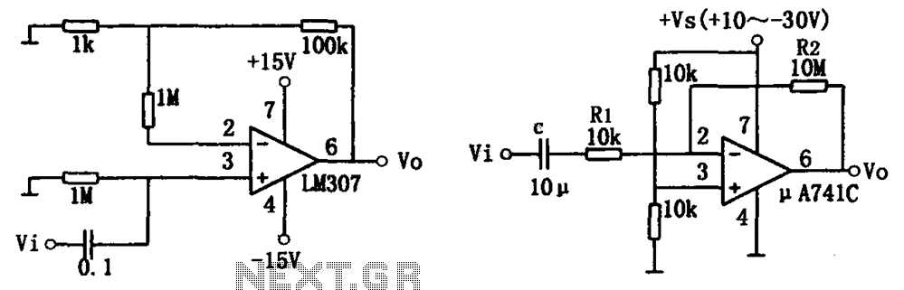
Simple audio amplifier LM307 A741
The simple audio amplifier circuit is illustrated in the figure. Utilizing an integrated op-amp configuration, this audio amplifier is stable and allows for easy negative feedback, facilitating the achievement of equalization characteristics. Additionally, the crosstalk between channels is minimal, making...
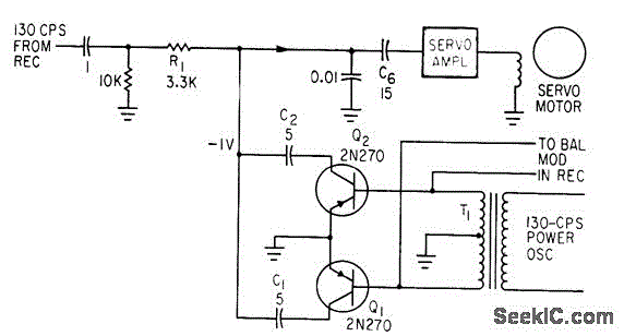
SYNCHRONOUS FILTER FOR ADF
Separates 130-cps motor drive voltage from voice frequencies in the output of an ADF receiver. P. V. Sparks, Servo Filter and Gain Control Improve Automatic Direction Finder, Electronics, 34:23, p 110-113.
The circuit described functions as a filter that effectively separates...
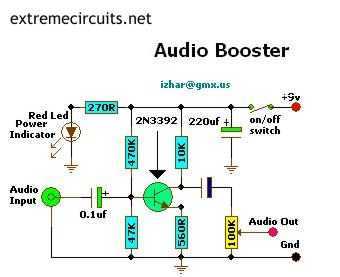
Mini Audio Booster Amplifier
This small amplifier circuit is ideal for boosting small audio units.
The small amplifier circuit is designed to enhance the audio signals from low-output devices, such as microphones or portable music players. It typically employs a transistor or an operational amplifier...
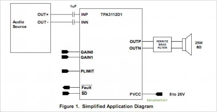
TPA3112D1 25-W FILTER-FREE MONO CLASS-D AUDIO POWER AMPLIFIER With SPEAKER GUARDß„
The TPS3803 and TPS3805 families of supervisory circuits offer circuit initialization and timing supervision, mainly for digital signal processors (DSPs) and processor-based systems. The TPS3803G15 device features a fixed-sense threshold voltage (VIT) determined by an internal voltage divider, while the...
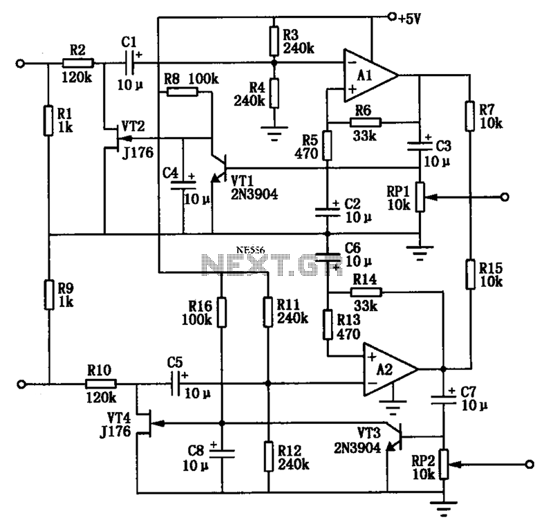
Audio AGC amplifier circuit
The Audio Automatic Gain Control (AGC) circuit monitors the output signal level of an audio preamplifier. When the input signal increases, the AGC circuit automatically reduces the amplifier's gain. Conversely, when the input signal decreases, the AGC circuit increases the...
ROTARY SWITCH DEBOUNCE
A three-stage active Butterworth bandpass input filter is utilized in a radioteletype demodulator to differentiate RTTY tones from one another and from noise. The filter is centered at 2200 Hz and has a bandwidth of approximately 260 Hz, allowing for...