


Advice on ground plane in my first PCB
#PCB design
#flyback controller
#LT3748
#transformer
#OrCAD
#ground plane
#class project
#power electronics
#connector
#layout
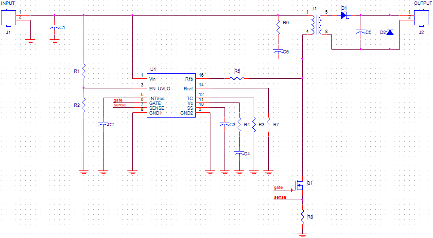
Description: The schematic is created using OrCAD Capture and is derived directly from the datasheet of the flyback controller LT3748. This project involves constructing a custom transformer. Due to the unavailability of the desired bobbin, the transformer will be placed adjacent to the circuit board and connected via a 4-pin connector. The layout cannot fully replicate the recommendations in the datasheet because a 2-layer design is being utilized for various reasons. Although a 4-layer design with a compact commercial SMT transformer would have been ideal, the project must proceed with the available resources. The datasheet emphasizes the importance of isolating or physically separating the high current ground from the small-signal ground. The secondary ground is already isolated, while the primary high-current grounds are associated with Vin and the sense resistor R8. The proposal is to connect the negative terminals of Vin and R8 with a track and then join that track to a ground plane that accommodates all other small-signal grounds. This approach may result in a longer track from R8 to Vin, as the 2-layer design limits the ability to maintain a continuous ground plane. Two tracks are currently routed beneath the integrated circuit (IC) on the same top layer. Concerns regarding potential issues with this configuration are raised, although the IC is expected to operate at low current levels, minimizing heat generation.
The schematic utilizes the LT3748 flyback controller, which is designed for applications requiring efficient power conversion. The controller features a built-in high-voltage startup circuit and a voltage feedback loop that regulates output voltage. The transformer design is critical, as it dictates the electrical characteristics of the flyback converter, including output voltage, current, and efficiency.
The decision to use a 2-layer PCB introduces certain limitations, especially regarding the separation of power and ground planes. In a typical design, a 4-layer PCB allows for more effective grounding strategies, reducing noise and improving performance. However, in this case, the separation of the high current ground from the small-signal ground is vital to minimize interference and ensure stable operation.
Connecting the negative terminals of Vin and R8 to a common track before joining them to the ground plane is a reasonable approach, provided that the track length is managed carefully. Longer tracks can introduce inductance and resistance, which may affect circuit performance, particularly in high-frequency applications. It is advisable to keep the track as short as possible while ensuring that the layout remains functional and adheres to the design constraints.
The layout's complexity increases with the routing of multiple tracks under the IC. While this can lead to potential thermal issues or crosstalk, it is manageable if the IC operates within its thermal limits. Adequate heat dissipation measures should be considered, such as thermal vias or additional copper area around the IC, to ensure that it remains within safe operating temperatures during all conditions.
Overall, the design should be validated through simulation and testing to confirm that the chosen layout and grounding strategy meet the performance expectations of the LT3748 flyback controller while accommodating the physical constraints of the project.Schematic drawn using OrCAD Capture, which is straight out of the datasheet of the flyback controller LT3748. This is a class project and we must build our own transformer. We couldn`t get the bobbin we wanted and so decided to just lay down the transformer somewhere next to the board and connected it through a 4-pin connector.
We couldn`t really mimic the layout suggested in the datasheet, as we`re using only a 2-layer design for various reasons. We do realize that a 4-layer design along with a small commercial SMT transformer would have been ideal, but we`re working with what we`ve got. The datasheet advises to isolate or physically separate the high current ground from small-signal ground.
The secondary ground is completely separate, so that`s done with. As for primary, the only high-current grounds are those of Vin and R8 (the sense resistor). So, is it a good idea to connect the negative terminals of Vin and R8 with a track and then connect that track at one point to a ground plane that will have all the other small-signal grounds. The only penalty then would be that the R8 to Vin track would be quite long (since I`m using 2-layer only and wouldn`t like to break my ground plane underneath, unless it is less worse than running this long track).
As you see from the schematic, I`m running two tracks underneath the IC (i. e. on the same top layer). Do you foresee any problems there My IC shouldn`t get hot, as it works with small current only.
The schematic utilizes the LT3748 flyback controller, which is designed for applications requiring efficient power conversion. The controller features a built-in high-voltage startup circuit and a voltage feedback loop that regulates output voltage. The transformer design is critical, as it dictates the electrical characteristics of the flyback converter, including output voltage, current, and efficiency.
The decision to use a 2-layer PCB introduces certain limitations, especially regarding the separation of power and ground planes. In a typical design, a 4-layer PCB allows for more effective grounding strategies, reducing noise and improving performance. However, in this case, the separation of the high current ground from the small-signal ground is vital to minimize interference and ensure stable operation.
Connecting the negative terminals of Vin and R8 to a common track before joining them to the ground plane is a reasonable approach, provided that the track length is managed carefully. Longer tracks can introduce inductance and resistance, which may affect circuit performance, particularly in high-frequency applications. It is advisable to keep the track as short as possible while ensuring that the layout remains functional and adheres to the design constraints.
The layout's complexity increases with the routing of multiple tracks under the IC. While this can lead to potential thermal issues or crosstalk, it is manageable if the IC operates within its thermal limits. Adequate heat dissipation measures should be considered, such as thermal vias or additional copper area around the IC, to ensure that it remains within safe operating temperatures during all conditions.
Overall, the design should be validated through simulation and testing to confirm that the chosen layout and grounding strategy meet the performance expectations of the LT3748 flyback controller while accommodating the physical constraints of the project.Schematic drawn using OrCAD Capture, which is straight out of the datasheet of the flyback controller LT3748. This is a class project and we must build our own transformer. We couldn`t get the bobbin we wanted and so decided to just lay down the transformer somewhere next to the board and connected it through a 4-pin connector.
We couldn`t really mimic the layout suggested in the datasheet, as we`re using only a 2-layer design for various reasons. We do realize that a 4-layer design along with a small commercial SMT transformer would have been ideal, but we`re working with what we`ve got. The datasheet advises to isolate or physically separate the high current ground from small-signal ground.
The secondary ground is completely separate, so that`s done with. As for primary, the only high-current grounds are those of Vin and R8 (the sense resistor). So, is it a good idea to connect the negative terminals of Vin and R8 with a track and then connect that track at one point to a ground plane that will have all the other small-signal grounds. The only penalty then would be that the R8 to Vin track would be quite long (since I`m using 2-layer only and wouldn`t like to break my ground plane underneath, unless it is less worse than running this long track).
As you see from the schematic, I`m running two tracks underneath the IC (i. e. on the same top layer). Do you foresee any problems there My IC shouldn`t get hot, as it works with small current only.
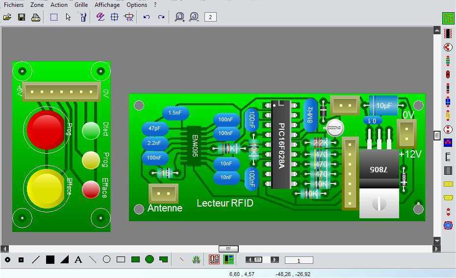
WinCircuit
WinCircuit is a software of realization of drawing of printed circuit in single or double layers. Principal qualities are the facility of use and the sight in pseudo 3D which gets a vision of the circuit close to reality. More:...
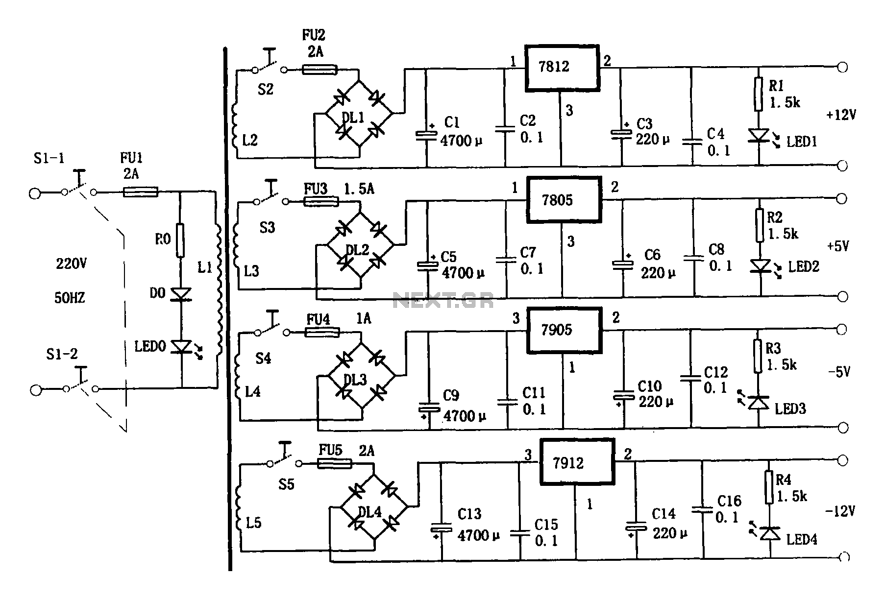
Multi-output power supply circuit
This document presents a multi-output power supply circuit. The circuit utilizes the secondary winding of a transformer and incorporates four voltage regulators: 7812, 7805, 7905, and 7912, providing independent output voltages of +12V, +5V, -5V, and -12V, respectively. Each output...
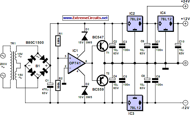
Triple Power Supply
Inexpensive miniature transformers typically provide one or two secondary voltages, which are sufficient for generating a set of positive and negative supply voltages, as required for operational amplifier circuits. However, if an additional voltage higher than either of the supply...
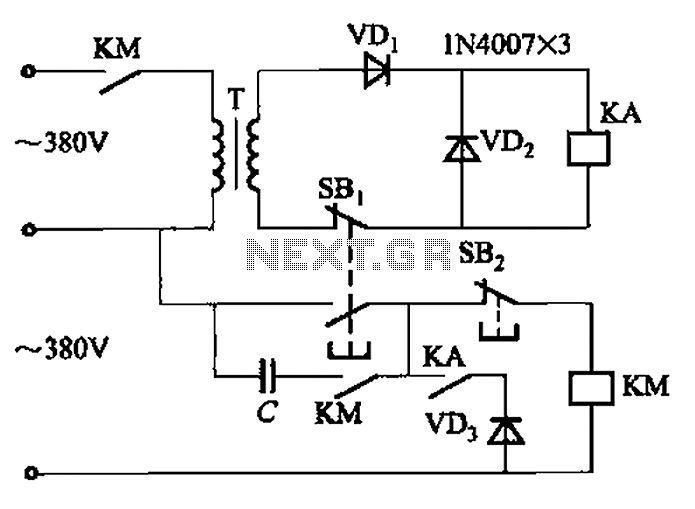
Transformer AC contactor DC operation circuit b
The AC contactor DC transformer circuit operates using various types of transformers and AC contactors in a DC application.
The AC contactor DC transformer circuit is designed to control and manage electrical power in applications where alternating current (AC) is converted...
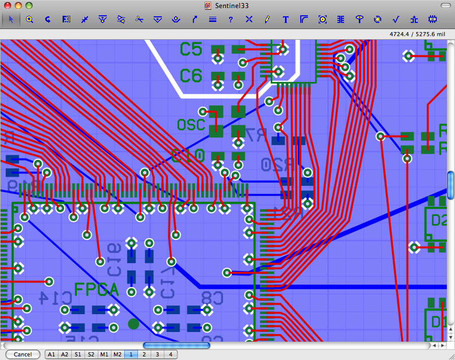
Osmond PCB
Osmond PCB is a flexible tool for designing printed circuit boards. It runs on Macintosh. Its many features include: * Virtually unlimited board sizes * Virtually unlimited number of board layers * Virtually unlimited number of parts.. More: * Spatial...

transformer circuit
A static device that couples two circuits to transfer alternating current (AC) from one circuit to another through electromagnetic induction. The current maintains the same frequency but may vary in voltage, phase, or impedance values. A transformer consists of two...
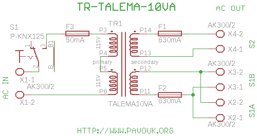
Talema 10VA transformer board
All DAC boards include a power supply section. It is sufficient to connect only a power transformer. This board is designed for a toroidal 10VA transformer manufactured by Talema, which features pins for PCB connection and exhibits minimal electromagnetic field...
Energy losses in modem
A toroidal transformer (2x12V 15VA) is utilized due to its significantly lower energy losses compared to an E-I core transformer, which was employed in the original mains adapter.
The toroidal transformer is a type of transformer that features a doughnut-shaped core...

DIY Circuit Car Battery Charger
This simple circuit consists of a transformer, two diodes, a capacitor, and an ammeter. To charge a battery, connect the positive and negative terminals of the circuit to the corresponding terminals of the battery. When the battery is not charged,...