


Application of the principle uPC1237H
#uPC1237H
#detector
#circuit protection
#voltage monitoring
#abnormal detection
#power management
#IC
#safety
#electronic components
#control circuit
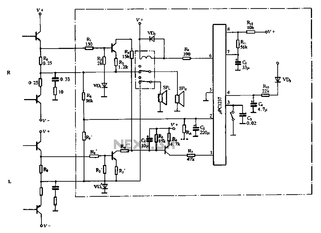
Description: The 1237H circuit principle is illustrated in Figure 2-122. It contains four distinct detectors that can independently perform their inspection tasks. In the event of a circuit abnormality, the system can immediately activate a relay to disconnect the output circuit, thereby protecting the speaker and associated circuitry from damage. The relay can drive an output current of up to 80 mA. The overload protection circuit and the midpoint voltage offset circuit have two reset methods: an automatic reset method, where pin 3 is grounded through a 0.02 µF capacitor, allowing the relay to release automatically after troubleshooting; and a manual reset method, where pin 3 is directly grounded, locking the circuit until it is manually reset. Both methods have their advantages and should be selected based on the application. The PC1237H operates on a single supply with a wide voltage range of 25V to 60V. The power protection circuit consists of resistors R2 and R21 and capacitor C11 (as shown in Figure 2-122). Pin 7 serves as the power protection input terminal. The voltage at pin Vc charges C11 through R21, and due to the timing of C5, the relay remains active after powering up until the pre-stage amplifier stabilizes, at which point the relay releases to connect to the speakers, preventing power surges. The delay time is determined by the equation C11-R21-ln[(V8-V7)/V8], resulting in a delay of 1.7 seconds. The midpoint offset protection circuit, consisting of resistor R14 and transistor Q (refer to Figure 2-122), has pin 2 as its input. The positive level detection threshold voltage is 0.62V, while the negative threshold voltage is 0.17V. Such high thresholds can lead to frequent relay activations, causing audible impacts; therefore, the overload protection circuit has been expanded, comprising resistors R15, R10, R11, and others (as depicted in Figure 2-122). Pin 1 serves as the overload protection input. When an overload occurs, the voltage drop across R6 increases, triggering transistor VT4 and subsequently activating the relay. The sensitivity of the protection can be adjusted by modifying resistor R10. The shutdown protection circuit includes components R9 and C12 (as shown in Figure 2-122), with pin 4 as the shutdown protection input. The power supply circuit rectifies the input through diode VD7 and regulates it via resistor R19, stabilizing the voltage at pin 4 after filtering through capacitor C4. If power is lost at pin 4, the relay will immediately activate. Due to the smaller capacitance of C12 compared to the power supply filter capacitor, the immediate loss of power at pin 4 effectively prevents shutdown impacts.
The 1237H circuit is designed for robust performance in various electronic applications, particularly where speaker protection is critical. The inclusion of multiple detection circuits allows for comprehensive monitoring and immediate response to anomalies, ensuring the longevity and reliability of connected components. The relay's dual reset options provide flexibility in operation, allowing users to choose between automatic and manual reset methods based on the specific requirements of their setup.
The power protection mechanism is crucial for preventing damage from power surges, and the delay feature ensures that the system stabilizes before re-engaging the speakers, thus mitigating the risk of audible pops or clicks that can occur during power transitions. The midpoint offset protection circuit plays a vital role in maintaining signal integrity and preventing false triggering of the relay due to minor fluctuations in voltage.
Overall, the 1237H circuit exemplifies a well-engineered solution for managing power and protecting sensitive audio components, with thoughtful design considerations that address both operational flexibility and reliability.1237H-circuit principle shown in Figure 2-122. Its interior has four separate detectors can finish respectively to their inspection tasks. When the circuit is abnormal, it can immediately drive the relay, disconnect the output circuit, speaker protection and associated circuitry from damage. Relay output drive current rvPC1237H up 80rnA, wherein the overload protection circuit, the midpoint voltage offset circuit protection reset in two ways, one is automatically reset method, namely 3 feet by a 0 - 02t.eF capacitance ground when the circuit failure relay, the relay is automatically released after troubleshooting.
Another species is shutdown reset method, namely 3 feet directly to ground, then self-locking function within the circuit, the relay pull once, even if it will not release when the fault disappears after the shutdown circuit must be reset. Two methods has its advantages. When should each use flexibly select oLePC1237H single-supply operation, the operating voltage range is very wide, 25V - 60V between can work reliably.
Power protection circuit consists Rzo, R2l, Cll composition (Fig 2-122 R12.Ri l and island), 7 feet for power protection input into the terminal. Vc by, R2l charge to cll after power. Since the time of action C5, the relay in the boot after the delay time remains active until the pre-stage amplifier stage and push into a stable state after the end of the time delay relay release, connected speakers, thus avoiding power impact.
Delay time from equation Cii-Rzl-ln [(V8 - V7)/V8] decision, according to the figure number, the delay time of 1.7 seconds. Midpoint offset by the protection circuit Rj4, islands (Fig. 2-122 in people, Q), 2 feet for protection midpoint voltage offset input. Its a positive level detection threshold voltage is 0 - 62V, the negative threshold voltage level detection is a 0.17V.
Such a high index, in practical applications can cause frequent movement of the relay, the impact sound effect, so in practice the protection of the electrical circuit path has expanded o overload protection circuit consists Vr5, VT4, Rio, Rl l and R etc. (Figure 2-122 for VTs, VT7, Ri, R2 and Ro), 1 pin overload protection input. When the output overload, the voltage drop across R6 increases, and this will trigger VT4 conducting a VTs conduction, thereby triggering a foot so that relay.
Adjusted odds of Rio and can be changed to protect sensitive Rl1 degrees. Shutdown protection circuit from anti- f, RL9 and C12 (Figure 2-122 for f wind, R10, C4), 4 feet for the shutdown protection input into the terminal. Working through the power supply circuit VD7 rectified when the buck by R19, to establish a stable straight 4 feet after filtering C4 stream level.
Just 4 feet a loss of power, the relay immediately pull. Since the C12 is much smaller than the capacity of the power supply filter capacitor, so if a shutdown pin 4 immediate loss of power, effectively preventing the shutdown impact o
The 1237H circuit is designed for robust performance in various electronic applications, particularly where speaker protection is critical. The inclusion of multiple detection circuits allows for comprehensive monitoring and immediate response to anomalies, ensuring the longevity and reliability of connected components. The relay's dual reset options provide flexibility in operation, allowing users to choose between automatic and manual reset methods based on the specific requirements of their setup.
The power protection mechanism is crucial for preventing damage from power surges, and the delay feature ensures that the system stabilizes before re-engaging the speakers, thus mitigating the risk of audible pops or clicks that can occur during power transitions. The midpoint offset protection circuit plays a vital role in maintaining signal integrity and preventing false triggering of the relay due to minor fluctuations in voltage.
Overall, the 1237H circuit exemplifies a well-engineered solution for managing power and protecting sensitive audio components, with thoughtful design considerations that address both operational flexibility and reliability.1237H-circuit principle shown in Figure 2-122. Its interior has four separate detectors can finish respectively to their inspection tasks. When the circuit is abnormal, it can immediately drive the relay, disconnect the output circuit, speaker protection and associated circuitry from damage. Relay output drive current rvPC1237H up 80rnA, wherein the overload protection circuit, the midpoint voltage offset circuit protection reset in two ways, one is automatically reset method, namely 3 feet by a 0 - 02t.eF capacitance ground when the circuit failure relay, the relay is automatically released after troubleshooting.
Another species is shutdown reset method, namely 3 feet directly to ground, then self-locking function within the circuit, the relay pull once, even if it will not release when the fault disappears after the shutdown circuit must be reset. Two methods has its advantages. When should each use flexibly select oLePC1237H single-supply operation, the operating voltage range is very wide, 25V - 60V between can work reliably.
Power protection circuit consists Rzo, R2l, Cll composition (Fig 2-122 R12.Ri l and island), 7 feet for power protection input into the terminal. Vc by, R2l charge to cll after power. Since the time of action C5, the relay in the boot after the delay time remains active until the pre-stage amplifier stage and push into a stable state after the end of the time delay relay release, connected speakers, thus avoiding power impact.
Delay time from equation Cii-Rzl-ln [(V8 - V7)/V8] decision, according to the figure number, the delay time of 1.7 seconds. Midpoint offset by the protection circuit Rj4, islands (Fig. 2-122 in people, Q), 2 feet for protection midpoint voltage offset input. Its a positive level detection threshold voltage is 0 - 62V, the negative threshold voltage level detection is a 0.17V.
Such a high index, in practical applications can cause frequent movement of the relay, the impact sound effect, so in practice the protection of the electrical circuit path has expanded o overload protection circuit consists Vr5, VT4, Rio, Rl l and R etc. (Figure 2-122 for VTs, VT7, Ri, R2 and Ro), 1 pin overload protection input. When the output overload, the voltage drop across R6 increases, and this will trigger VT4 conducting a VTs conduction, thereby triggering a foot so that relay.
Adjusted odds of Rio and can be changed to protect sensitive Rl1 degrees. Shutdown protection circuit from anti- f, RL9 and C12 (Figure 2-122 for f wind, R10, C4), 4 feet for the shutdown protection input into the terminal. Working through the power supply circuit VD7 rectified when the buck by R19, to establish a stable straight 4 feet after filtering C4 stream level.
Just 4 feet a loss of power, the relay immediately pull. Since the C12 is much smaller than the capacity of the power supply filter capacitor, so if a shutdown pin 4 immediate loss of power, effectively preventing the shutdown impact o
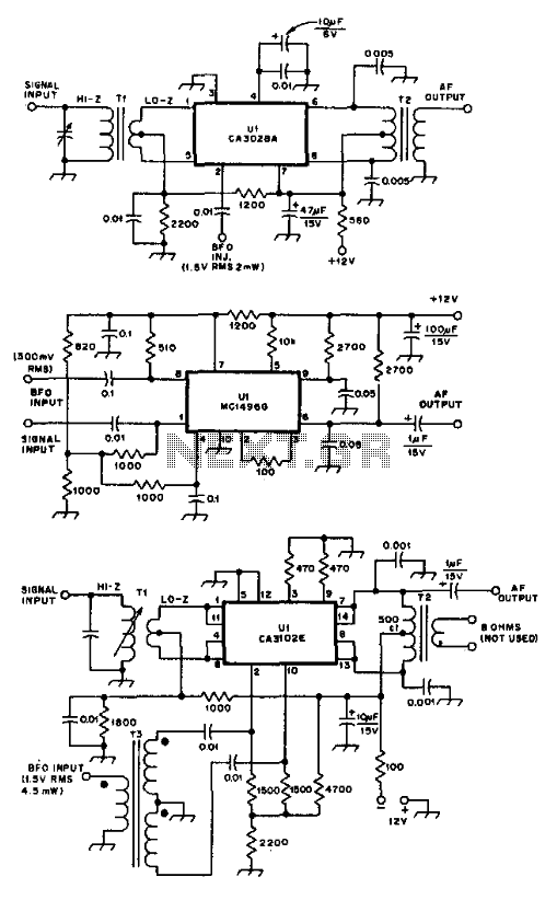
Ic Product Detectors
These product detectors utilize integrated circuit (IC) devices. They are capable of detecting single sideband (SSB) and continuous wave (CW) signals. The circuits are designed to operate effectively up to frequencies of 20 or 30 MHz. T3 in the schematic...
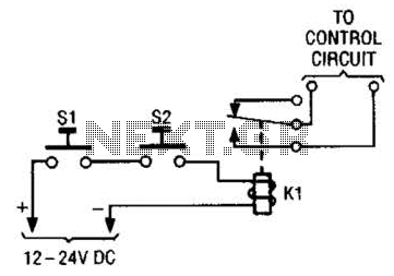
Simple Safety Circuit Circuit
The simple two-hand safety control switch consists of two pushbutton switches connected in series; both must be depressed to energize the relay.
The two-hand safety control switch is designed to enhance safety in applications where the operation of machinery or equipment...
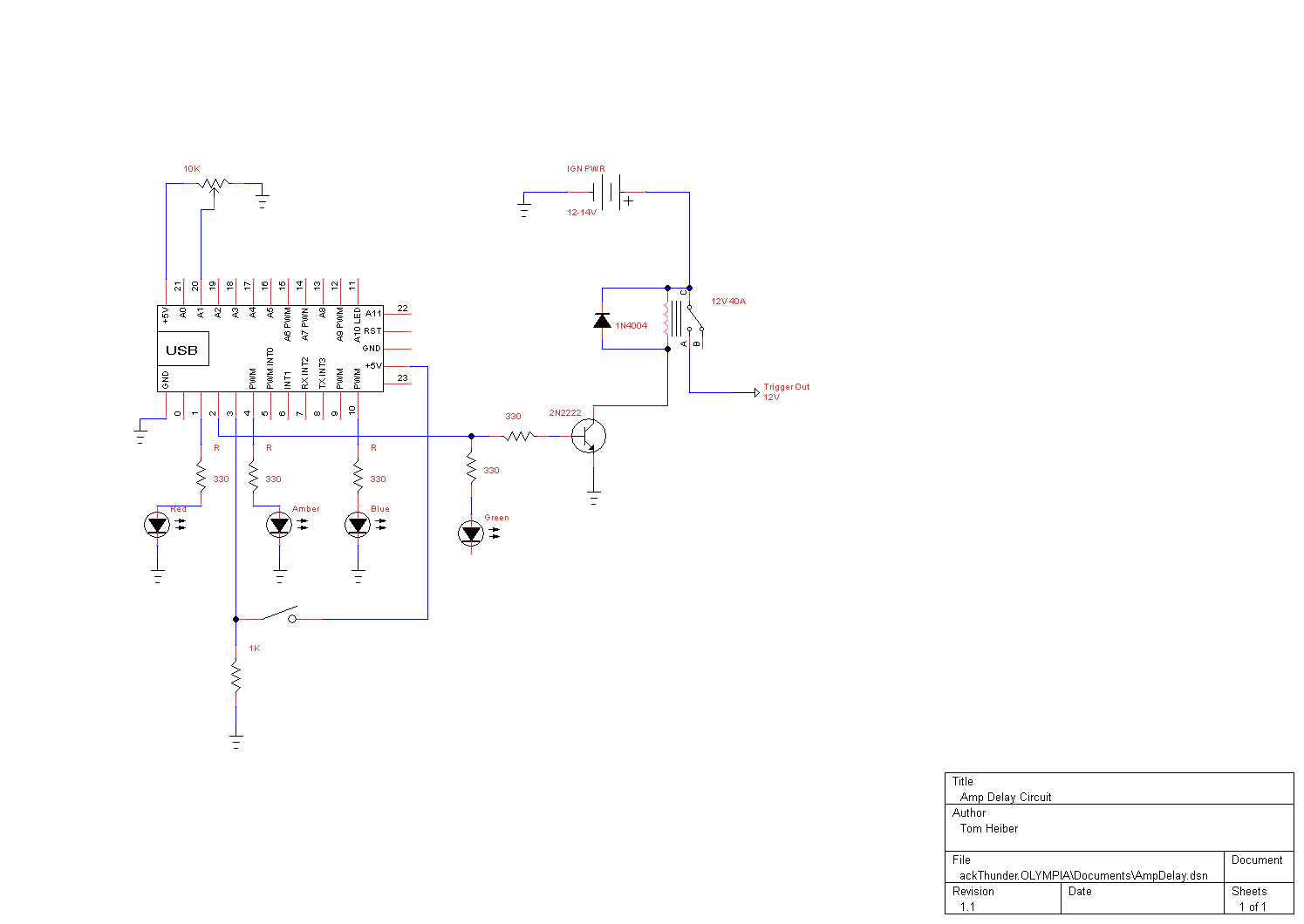
smart amp delay
This system is designed as a Windows service that detects various power events, including Suspend, Hibernate, Reboot, and Shutdown. It can send appropriate responses to a control circuit, specifically a Heartbeat or Kill signal. The trigger mechanism is also regulated...
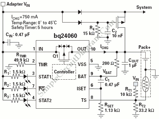
Power Path Management Battery Charger
Powering the system is required by many applications while charging the battery simultaneously. Interaction between the system and charger may result in a...
Power management in electronic systems is critical, particularly in applications that necessitate simultaneous operation and battery charging. This...
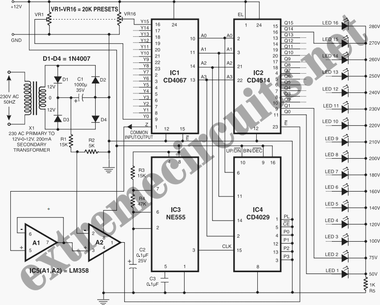
Digital Main Voltage Indicator
Continuous monitoring of mains voltage is essential in various applications, including manual voltage stabilizers and motor pumps. Although an analog voltmeter is cost-effective, it has several drawbacks due to its moving parts and sensitivity to vibrations. The solid-state voltmeter circuit...
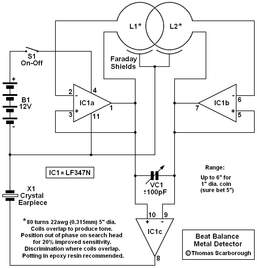
Detector switch circuits
A simple test circuit designed for troubleshooting audio and radio equipment. It can inject a square wave signal rich in harmonics or be used with headphones as an audio tracer. A single-pole double-throw switch is utilized to toggle between injection...

A Power Management Interface Circuit For Telecom Hot Swap With Local Dc/dc Conve
New cellular phones have incorporated high-resolution cameras that require bright illumination of the surrounding area to achieve high-quality pictures. Traditional xenon-filled photo flashes cannot be used due to the limited space available in cellular phone cameras. Instead, design engineers utilize...
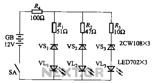
DC supply voltage the more limited indication circuit
When the supply voltage falls below 10.2V, the yellow light-emitting diode (LED) VLi illuminates, indicating that the storage pool can no longer continue to discharge. Additionally, when the voltage exceeds 16.2V, the yellow, green, and red light-emitting diodes (LEDs) VLi,...
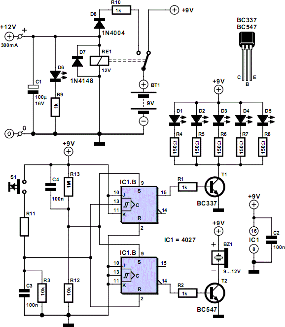
Mains Voltage Monitor
When the push button is pressed, a clock pulse appears on the CLK input of flip-flop IC1b. The output then toggles, causing the LEDs to turn off. Simultaneously, IC1a is reset, silencing the buzzer. Pressing the button again will turn...