


Battery powered Pi and servo switch
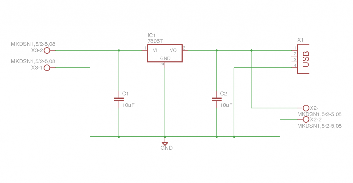
Description: This document outlines the details of several circuits designed and built for a robot. The first circuit is a voltage regulator intended to supply power to a Raspberry Pi from a 7.2V battery. While the circuit is relatively simple, it incorporates features that enhance usability for powering the Raspberry Pi.
The voltage regulator circuit for the Raspberry Pi is designed to convert the 7.2V from the battery to a stable 5V output, which is the required operating voltage for the Raspberry Pi. The circuit typically utilizes a linear voltage regulator, such as the LM7805, which is capable of providing a maximum output current of 1A.
The circuit configuration includes input and output capacitors to ensure stability and reduce voltage spikes. A capacitor with a value of 0.33 µF is placed at the input of the regulator to filter any high-frequency noise from the battery supply, while a 0.1 µF capacitor is placed at the output to maintain stability under varying load conditions.
Additionally, to enhance the circuit's performance, a heat sink may be attached to the voltage regulator to dissipate excess heat generated during operation, especially when the input voltage is significantly higher than the output voltage. This is crucial to prevent thermal shutdown, which can occur if the regulator overheats.
To facilitate easy connection to the Raspberry Pi, the output of the regulator can be connected to the 5V and GND pins of the Raspberry Pi GPIO header. The circuit can also be equipped with an LED indicator to show when the regulator is powered and functioning correctly.
Overall, this voltage regulator circuit is a practical solution for powering a Raspberry Pi from a higher voltage battery source, ensuring stable operation while integrating user-friendly features.This post will outline the details of a couple of circuits I designed and built for my robot. The first is a regulator to supply my Raspberry Pi with power from a 7.2V battery. Although a simple circuit, it has some features that make it very easy to use to power the pi.
The voltage regulator circuit for the Raspberry Pi is designed to convert the 7.2V from the battery to a stable 5V output, which is the required operating voltage for the Raspberry Pi. The circuit typically utilizes a linear voltage regulator, such as the LM7805, which is capable of providing a maximum output current of 1A.
The circuit configuration includes input and output capacitors to ensure stability and reduce voltage spikes. A capacitor with a value of 0.33 µF is placed at the input of the regulator to filter any high-frequency noise from the battery supply, while a 0.1 µF capacitor is placed at the output to maintain stability under varying load conditions.
Additionally, to enhance the circuit's performance, a heat sink may be attached to the voltage regulator to dissipate excess heat generated during operation, especially when the input voltage is significantly higher than the output voltage. This is crucial to prevent thermal shutdown, which can occur if the regulator overheats.
To facilitate easy connection to the Raspberry Pi, the output of the regulator can be connected to the 5V and GND pins of the Raspberry Pi GPIO header. The circuit can also be equipped with an LED indicator to show when the regulator is powered and functioning correctly.
Overall, this voltage regulator circuit is a practical solution for powering a Raspberry Pi from a higher voltage battery source, ensuring stable operation while integrating user-friendly features.This post will outline the details of a couple of circuits I designed and built for my robot. The first is a regulator to supply my Raspberry Pi with power from a 7.2V battery. Although a simple circuit, it has some features that make it very easy to use to power the pi.
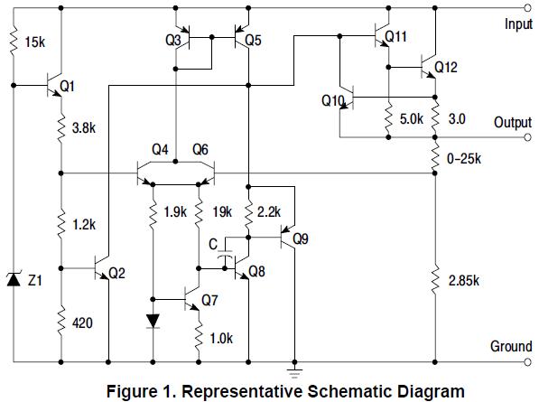
MC78L15ABPG Original supply
MC78L15ABPG positive voltage regulator, 100mA, TO-92
The MC78L15ABPG is a low-dropout (LDO) voltage regulator designed to provide a stable output voltage of 15V with a maximum output current of 100mA. This device is packaged in a TO-92 form factor, which is...
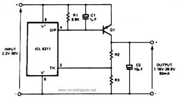
positive voltage regulator circuit with
The IC8211 serves as a voltage reference and regulator amplifier, with Q1 likely functioning as the series pass transistor. R1 determines the output current of the IC8211, while C1 and C2 contribute to loop stability and help suppress the feedthrough...
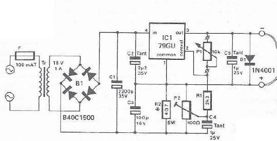
mini drill speed regulator
An integrated voltage regulator connected in reverse to a mini drill allows for speed adjustment within specific limits, maintaining a constant speed regardless of load. The electronic speed control is achieved through a voltage regulator, which can power motors requiring...
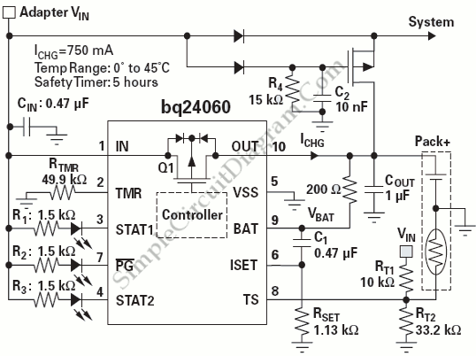
Power Path Management Battery Charger
Powering the system is required by many applications while charging the battery simultaneously. Interaction between the system and charger may result in a...
Power management in electronic systems is critical, particularly in applications that necessitate simultaneous operation and battery charging. This...
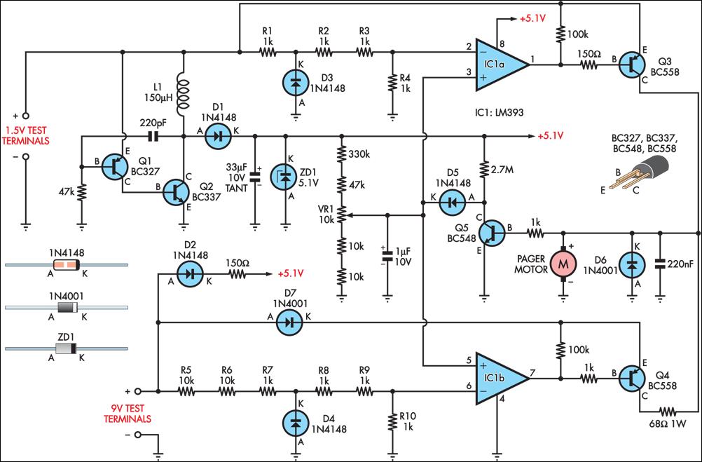
improved vibrating battery
Many blind and deaf-blind individuals utilize portable electronic devices to assist in their daily activities; however, testing the batteries used in such equipment can be challenging. While talking voltmeters are available for the blind, there is no commercially available equivalent...
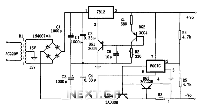
Temperature compensation of the symmetrical power supply 7812 F007C
The circuit is a temperature-compensated power supply that generates a negative voltage to track positive voltage changes in a symmetrical voltage integrated power supply. It features a three-terminal regulator connected with two identical transistors, leveraging the temperature characteristics of the...
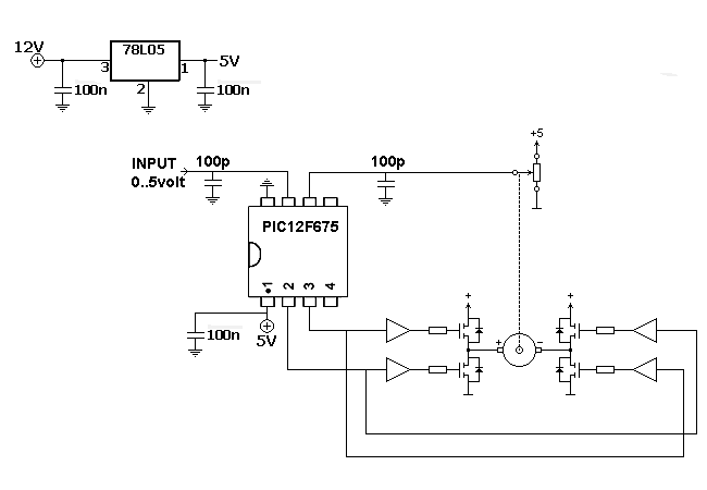
Servo CDI Programmable Digital Ignition
The motor is utilized to provide the mechanical output of the system and to move the potentiometer for loop closure. For high-power servos, three-phase motors can be employed. Potentiometer: A simple potentiometer can be used for standard industrial applications to...
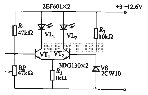
Battery discharge status indicator circuit
When the battery voltage is within the range of 7 to 12.6V, the light-emitting diode VLi illuminates, maintaining a consistent brightness. If the battery voltage drops below 7V, VLi begins to emit a red light, and the brightness of the...
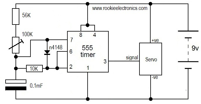
servo speed tester
This is likely the simplest circuit to test a servo. It tests the speed of the servo using a potentiometer to control the speed. By applying a low voltage, such as 4.5V, and adjusting the potentiometer value, the position of...