


Bridge rectifier circuit in the electronic ballast application circuit
#bridge rectifier
#electronic ballast
#AC to DC
#rectification
#power conversion
#diode
#circuit design
#electrical engineering
#energy efficiency
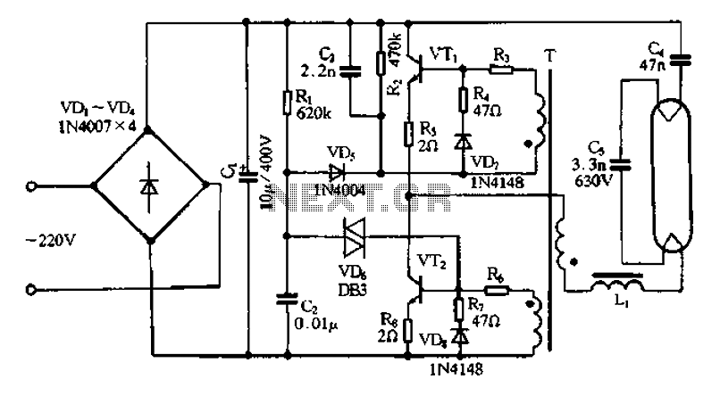
Description: Bridge rectifier circuit in the electronic ballast application circuit
The bridge rectifier circuit is a crucial component in electronic ballast applications, primarily utilized for converting alternating current (AC) to direct current (DC). This conversion is essential for powering various electronic devices, particularly in lighting systems where precise control of current is necessary for optimal performance.
The typical configuration of a bridge rectifier consists of four diodes arranged in a bridge topology. This arrangement allows both halves of the AC waveform to be utilized, effectively doubling the output voltage and improving efficiency. The diodes are connected in such a way that during the positive half-cycle of the AC input, two diodes conduct and allow current to flow through the load in one direction. During the negative half-cycle, the other two diodes conduct, again allowing current to flow through the load in the same direction. This results in a pulsating DC output.
In an electronic ballast application, the bridge rectifier is often followed by a smoothing capacitor, which serves to reduce the ripple voltage in the output. This capacitor stores energy during the peaks of the rectified voltage and releases it during the troughs, providing a more stable DC voltage to the subsequent circuitry. Additionally, voltage regulators may be employed to further stabilize the output voltage and ensure compatibility with the electronic components being powered.
The design of the bridge rectifier must take into account the maximum input voltage and current ratings, as well as the thermal management of the diodes to prevent overheating. Proper selection of diode specifications, such as reverse voltage rating and forward current rating, is essential to ensure reliable operation under varying load conditions.
Overall, the bridge rectifier circuit plays a vital role in the functionality of electronic ballasts by enabling efficient energy conversion and stable power delivery to lighting systems, thereby contributing to energy savings and enhanced performance in lighting applications. Bridge rectifier circuit in the electronic ballast application circuit
The bridge rectifier circuit is a crucial component in electronic ballast applications, primarily utilized for converting alternating current (AC) to direct current (DC). This conversion is essential for powering various electronic devices, particularly in lighting systems where precise control of current is necessary for optimal performance.
The typical configuration of a bridge rectifier consists of four diodes arranged in a bridge topology. This arrangement allows both halves of the AC waveform to be utilized, effectively doubling the output voltage and improving efficiency. The diodes are connected in such a way that during the positive half-cycle of the AC input, two diodes conduct and allow current to flow through the load in one direction. During the negative half-cycle, the other two diodes conduct, again allowing current to flow through the load in the same direction. This results in a pulsating DC output.
In an electronic ballast application, the bridge rectifier is often followed by a smoothing capacitor, which serves to reduce the ripple voltage in the output. This capacitor stores energy during the peaks of the rectified voltage and releases it during the troughs, providing a more stable DC voltage to the subsequent circuitry. Additionally, voltage regulators may be employed to further stabilize the output voltage and ensure compatibility with the electronic components being powered.
The design of the bridge rectifier must take into account the maximum input voltage and current ratings, as well as the thermal management of the diodes to prevent overheating. Proper selection of diode specifications, such as reverse voltage rating and forward current rating, is essential to ensure reliable operation under varying load conditions.
Overall, the bridge rectifier circuit plays a vital role in the functionality of electronic ballasts by enabling efficient energy conversion and stable power delivery to lighting systems, thereby contributing to energy savings and enhanced performance in lighting applications. Bridge rectifier circuit in the electronic ballast application circuit
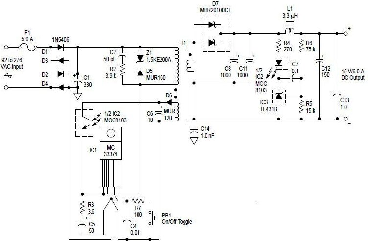
AC to DC 90 Watt Switching Power Adaptor PCB
An AC to DC switching power adapter circuit with a maximum output power of 90W. The switching power supply is constructed using a high voltage power switching regulator IC, the MC33374, along with several additional components. The MC33374 IC is...
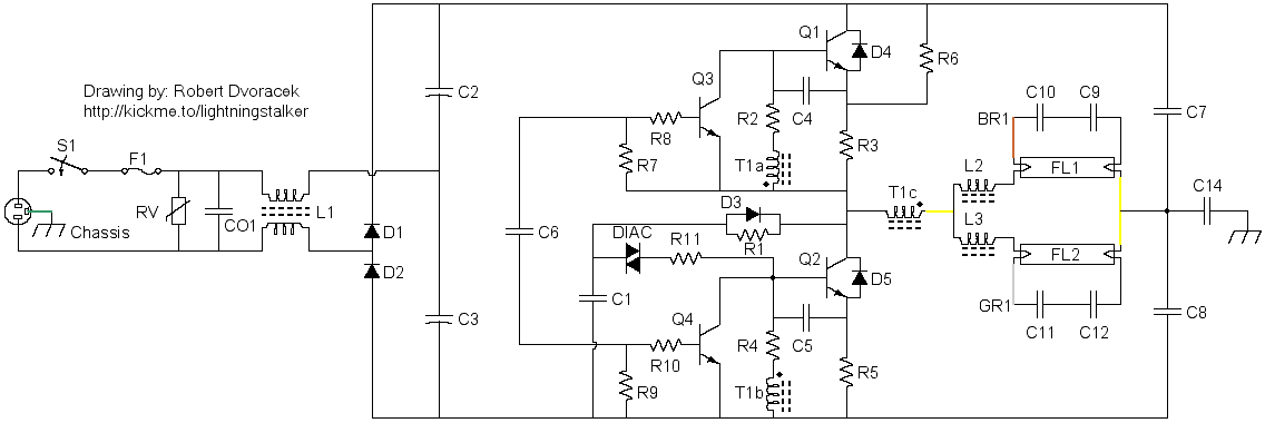
80W Electronic Ballast
Schematics for an 80W electronic ballast to drive two 48-inch lamps.
The electronic ballast circuit is designed to efficiently operate two 48-inch fluorescent lamps with a total power output of 80 watts. The schematic typically includes several key components that are...
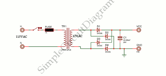
Low Voltage Power Supply
This is a power supply circuit that produces a voltage range of 12 to 24 V. It is straightforward, requiring only a bridge rectifier, a filter capacitor, and a transformer, without the need for a regulator. A bridge rectifier utilizes...
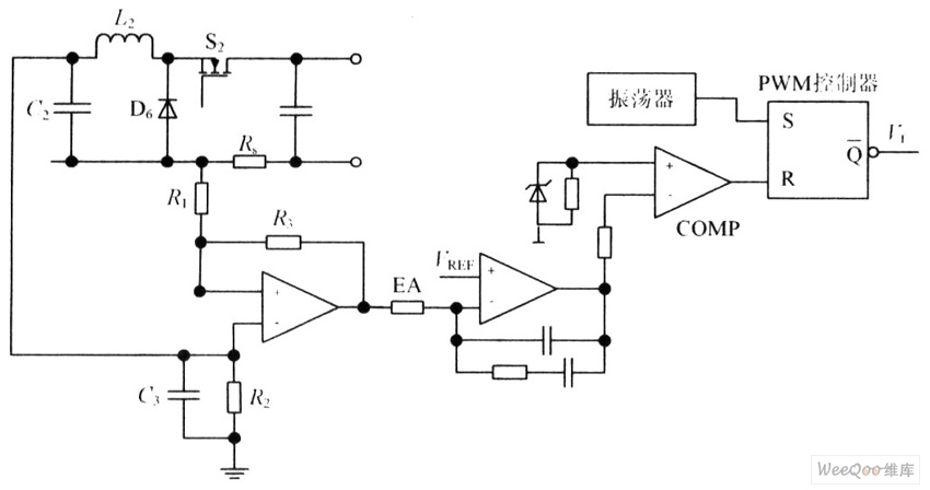
Metal halide electronic ballast constant power control circuit diagram
The circuit is capable of enhancing the system power factor to a value exceeding 0.99. It effectively reduces the waveform distortion of the input supply current, ensuring compliance with GB15144 standards, with a distortion index lower than level L. Additionally,...
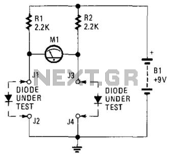
Diode Matching Circuit
This circuit can be utilized to match diodes for applications where balance is essential, such as in a balanced modulator. The diode matching circuit will display the forward voltage drop of the two diodes in millivolts.
The diode matching circuit is...
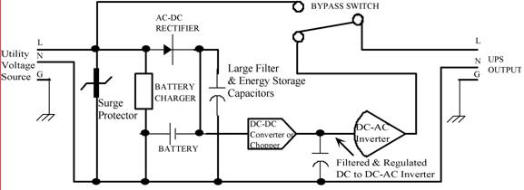
POWER FREQUENCY CONVERSION CONSIDERATIONS
Thomas Edison developed the incandescent light bulb, which operated from a 110-volt DC source. The primary drawback of DC power was that it could only be distributed over short distances without needing to be regenerated. In the early 1900s, when...
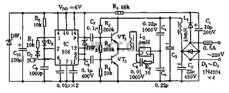
Electronic Ballast circuit diagram
The circuit operates as an electronic ballast for fluorescent lamps, incorporating a rectifier filter circuit, a high-frequency oscillation circuit, and an output circuit. The rectifier filter circuit consists of a rectifier diode (VD1) and filter capacitors (C1, C2). The high-frequency...
Power Up!
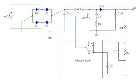
The design of the AC to DC front stage boost converter in discontinuous mode involved several steps. Initially, the specifications were defined. Subsequently, research was conducted, and the basic power factor correction circuit was analyzed. Finally, the boost converter stage...
case stepper
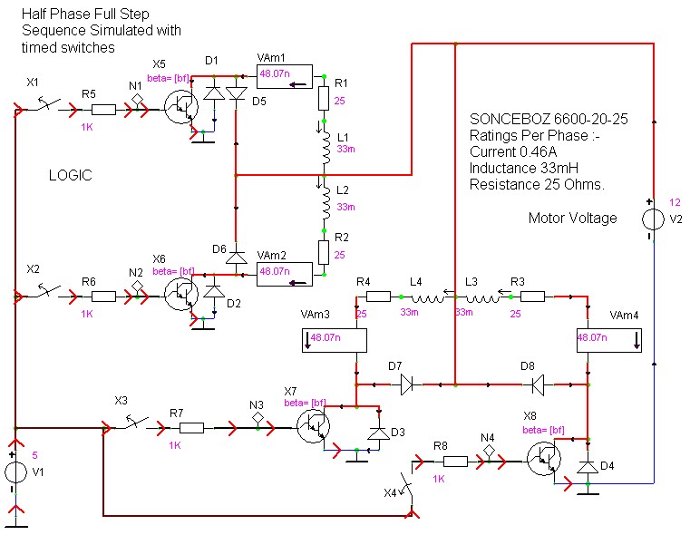
Beige Bag Software has been offering affordable and innovative circuit design tools since 1990. B2 Spice provides schematics as well as analog, digital, and mixed-mode electronic circuit simulation. It integrates with EAGLE and CADSTAR PCB software.
B2 Spice is a powerful...