


car cigar lighter to usb power socket circuit
#USB
#5V
#DC
#car adapter
#voltage regulator
#power converter
#cigar lighter
#portable devices
#electronics
#automotive
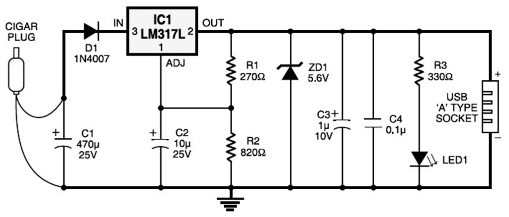
Description: A USB port is capable of supplying more than 100 mA of continuous electric current at 5V to peripherals connected to the bus. This feature allows a USB port to power 5V DC-operated small electronic devices without issues. Many handheld gadgets, such as portable reading lamps, utilize this resource to recharge their built-in battery packs with the help of internal circuitry. Typically, a 5V DC, 100mA electric current is required to meet the input power demand. The accompanying diagram illustrates a versatile USB power socket that effectively converts 12V battery voltage into stable 5V. This circuit enables the powering or recharging of any USB-powered device using the in-dash cigarette lighter socket of a car. Capacitor C1 buffers any disturbances in the input supply. Resistors R1 and R2 regulate the output of IC1 to maintain a constant 5V, which is available at the A-type female USB socket. Red LED1 indicates the output status, while zener diode ZD1 serves as a protector against excessive voltage. The circuit should be assembled on a general-purpose PCB and enclosed within a slim plastic cabinet, along with the indicator and USB socket. When wiring the USB outlet, it is essential to ensure the correct polarity of the supply. For interconnection between the cigar plug pin and the device, a long coiled cord should be used as shown in the second image.
The USB power socket circuit is designed to convert a 12V input from a car battery into a stable 5V output suitable for USB-powered devices. The circuit comprises several key components that work together to ensure reliable operation. The input voltage from the car's battery is first filtered by capacitor C1, which smooths out any fluctuations or noise, providing a clean voltage source to the subsequent components.
The core of the circuit is IC1, which is typically a voltage regulator designed to output a constant 5V. Resistors R1 and R2 form a voltage divider that sets the output voltage level of IC1, ensuring it remains stable under varying load conditions. This stability is crucial for the proper functioning of USB devices, which can be sensitive to voltage variations.
The inclusion of red LED1 serves a dual purpose; it not only indicates when the circuit is powered and operational but also provides a visual cue for troubleshooting if the LED does not illuminate. Zener diode ZD1 is an essential protective component, safeguarding the circuit from voltage spikes that could damage both the power socket and the connected devices.
For assembly, the circuit should be mounted on a general-purpose PCB, which provides a sturdy platform for the components and facilitates easy connections. The enclosure in a slim plastic cabinet protects the circuit from physical damage and environmental factors while allowing for adequate ventilation to dissipate any heat generated during operation.
Proper wiring of the USB outlet is critical; incorrect polarity can lead to circuit failure or damage to connected devices. Therefore, care should be taken to verify connections before powering the circuit. The use of a long coiled cord for interconnection between the cigar plug and the device enhances flexibility and ease of use, allowing users to position their devices conveniently while ensuring a secure connection.A USB port, in practice, is capable of supplying more than 100 mA of continuous electric current at 5V to the peripherals which are hooked up with the bus. So a USB port could be utilized, without having any problems, for powering 5V DC operated tiny electronic devices.
Today, a lot of handheld gadgets (for example, portable reading lamps) utilise this resource of the USB port to recharge their built-in battery pack using the support of an internal circuitry. Typically 5V DC, 100mA electric current is needed to satisfy the input electrical power demand. The above diagram shows the circuit of a versatile USB power socket that properly converts the 12V battery voltage into stable 5V. This circuit can make it possible to power / recharge any USB power-operated device, working with in-dash board cigar lighter socket of the car.
Capacitor C1 buffers any disorder in the input supply. Resistors R1 and R2 regulate the output of IC1 to constant 5V, that is accessible at the A` type female USB socket. Red LED1 signifies the output condition and zener diode ZD1 acts as a protector against excessive voltage.
Assemble the circuit on a general purpose PCB and enclose inside a slim plastic cabinet as well as the indicator and USB socket. Whilst wiring the USB outlet, make sure proper polarity of the supply. For interconnection between the cigar plug pin as well as the device, use a long coil cord as shown in second image.
The USB power socket circuit is designed to convert a 12V input from a car battery into a stable 5V output suitable for USB-powered devices. The circuit comprises several key components that work together to ensure reliable operation. The input voltage from the car's battery is first filtered by capacitor C1, which smooths out any fluctuations or noise, providing a clean voltage source to the subsequent components.
The core of the circuit is IC1, which is typically a voltage regulator designed to output a constant 5V. Resistors R1 and R2 form a voltage divider that sets the output voltage level of IC1, ensuring it remains stable under varying load conditions. This stability is crucial for the proper functioning of USB devices, which can be sensitive to voltage variations.
The inclusion of red LED1 serves a dual purpose; it not only indicates when the circuit is powered and operational but also provides a visual cue for troubleshooting if the LED does not illuminate. Zener diode ZD1 is an essential protective component, safeguarding the circuit from voltage spikes that could damage both the power socket and the connected devices.
For assembly, the circuit should be mounted on a general-purpose PCB, which provides a sturdy platform for the components and facilitates easy connections. The enclosure in a slim plastic cabinet protects the circuit from physical damage and environmental factors while allowing for adequate ventilation to dissipate any heat generated during operation.
Proper wiring of the USB outlet is critical; incorrect polarity can lead to circuit failure or damage to connected devices. Therefore, care should be taken to verify connections before powering the circuit. The use of a long coiled cord for interconnection between the cigar plug and the device enhances flexibility and ease of use, allowing users to position their devices conveniently while ensuring a secure connection.A USB port, in practice, is capable of supplying more than 100 mA of continuous electric current at 5V to the peripherals which are hooked up with the bus. So a USB port could be utilized, without having any problems, for powering 5V DC operated tiny electronic devices.
Today, a lot of handheld gadgets (for example, portable reading lamps) utilise this resource of the USB port to recharge their built-in battery pack using the support of an internal circuitry. Typically 5V DC, 100mA electric current is needed to satisfy the input electrical power demand. The above diagram shows the circuit of a versatile USB power socket that properly converts the 12V battery voltage into stable 5V. This circuit can make it possible to power / recharge any USB power-operated device, working with in-dash board cigar lighter socket of the car.
Capacitor C1 buffers any disorder in the input supply. Resistors R1 and R2 regulate the output of IC1 to constant 5V, that is accessible at the A` type female USB socket. Red LED1 signifies the output condition and zener diode ZD1 acts as a protector against excessive voltage.
Assemble the circuit on a general purpose PCB and enclose inside a slim plastic cabinet as well as the indicator and USB socket. Whilst wiring the USB outlet, make sure proper polarity of the supply. For interconnection between the cigar plug pin as well as the device, use a long coil cord as shown in second image.
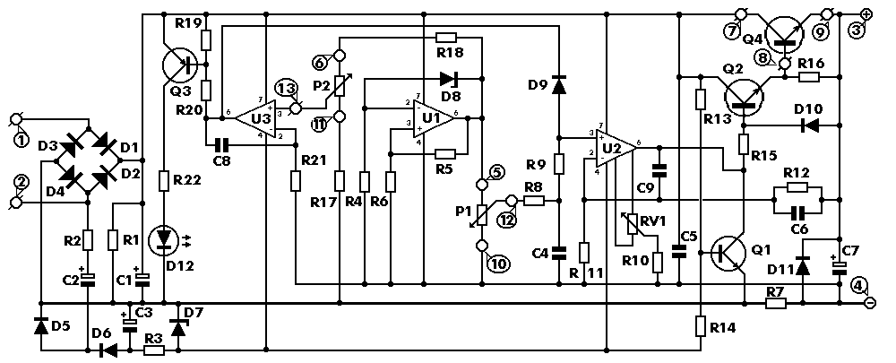
0-30 VDC Stabilized power supply with current control 0.002-3 A
This is a high quality power supply with a continuously variable stabilised output adjustable at any value between 0 and 30VDC. The circuit also incorporates an electronic output current limiter that effectively controls the output current from a few milliamperes...
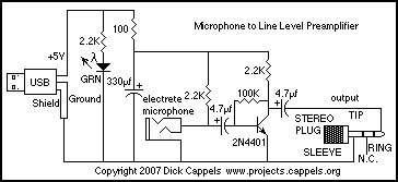
USB Microphone Line Level Preamp
The computer needs at least 180 millivolts peak-to-peak and the condenser microphone in my headset produces about 20 millivolts peak-to-peak into a 2.2k load with normal speech levels. There are USB ports on the machines, so I can use that...
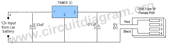
usb car charger
This project involves a mini USB car charger circuit that is simple to construct using only three components. The core of the circuit is the LM78M05 integrated circuit (IC), which is a 5V positive voltage regulator. This IC includes several...
stabilizer circuit
This circuit functions as a high-quality power supply with a continuously variable stabilized output that can be adjusted to any value between 0 and 30 VDC. It includes an electronic output current limiter that effectively regulates the output current from...
.jpg "FT232 USB to Serial Module circuit")
FT232 USB to Serial Module
This project utilizes the FT232XX chip series, which functions as a USB to serial converter. These chips are capable of converting USB protocol into asynchronous serial protocol, effectively allowing the transformation of a USB1 port into a corresponding serial port....
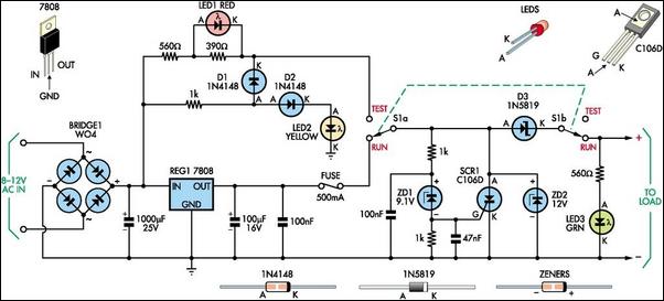
8V DC Power Supply With Over Voltage Protection
This 8V DC power supply is designed for use with high-end electronic equipment. It includes full over-voltage protection to safeguard against regulator failure, whether in the supply itself or in the connected device. The circuit employs a standard full-wave rectifier,...
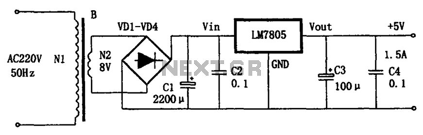
LM7805 + 5V power supply configuration
The circuit illustrated in the figure provides an output voltage of +5V and an output current of 1.5A. It comprises a power transformer, a bridge rectifier circuit consisting of diodes D1 to D4, and filter capacitor C1. Additionally, capacitors C2...
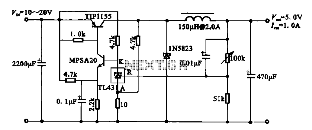
5V regulator circuit
The 5V regulator circuit is designed to convert a DC input voltage ranging from 10V to 20V into a stable 5V output. This circuit features low power consumption and high efficiency.
The 5V regulator circuit typically employs a linear voltage regulator...
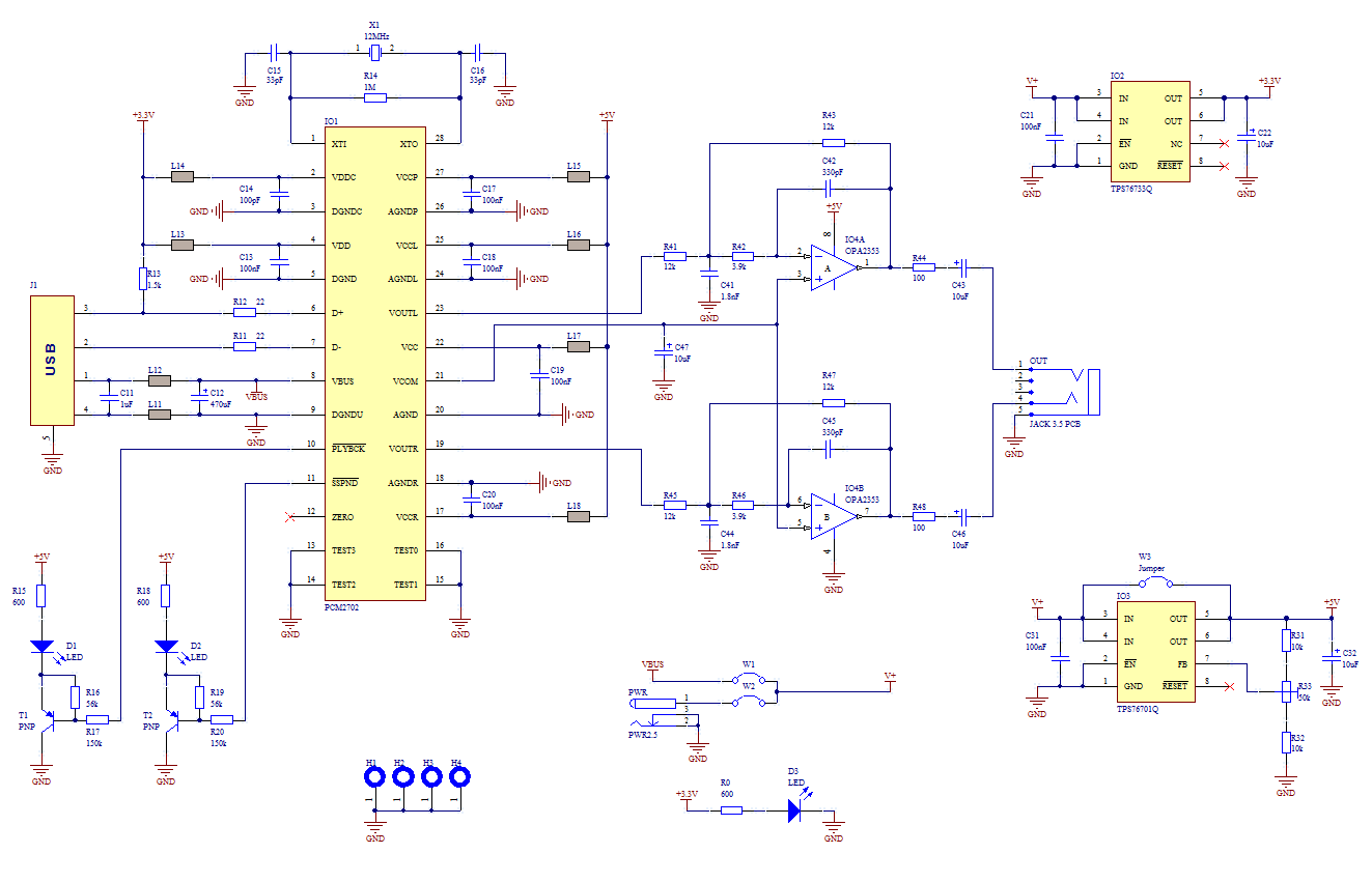
USB Sound Card
The core of this construction is 16-Bit Stereo Digital-To-Analog Converter with USB interface PCM2702. PCM2702 needs only a few additional parts to work. The schematic is not complex. The sound card can be powered directly from the USB port (jumper...