


Charge-pool-power-supply
#charge pool
#4-20mA
#current loop
#remote transmitter
#pulsed mode
#power supply
#sensor
#transmitter system
#energy storage
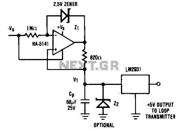
Description: It is generally advantageous for the remote transmitter of a 4 to 20 mA current loop system to be powered directly from the transmission line. However, in certain scenarios, high power demands of the remote sensor/transmitter system may preclude this option. An alternative to using a separate power supply can be implemented if the remote transmitter operates in a pulsed mode, activating only briefly to perform its functions. In such cases, a charge pool power supply can enable the transmitter to be powered directly by the current loop. In this circuit, a constant current (I1) is supplied to the charge pool capacitor (CP) from the HA-5141, with I1 approximately equal to 3 mA. The voltage (V1) across the capacitor continues to increase until the output of the HA-5141 approaches the positive supply voltage (V+), or until it reaches the optional voltage limiting provided by Z2. The LM2931 voltage regulator then provides the transmitter with a stable +5 V supply derived from the charge accumulated in CP. The available power supply current is determined by the duration of the pulse, the allowable voltage droop on CP, and the required repetition rate.
In the described circuit, a 4 to 20 mA current loop serves as the primary means of communication and power supply for the remote transmitter. The design leverages a charge pool capacitor (CP) to store energy, allowing the transmitter to operate intermittently. The HA-5141 operational amplifier functions as a current source, providing a constant current (I1) to the capacitor. The choice of I1 at approximately 3 mA is critical, as it ensures that CP charges sufficiently during its active state without exceeding the power limitations of the system.
As the capacitor charges, the voltage (V1) across it rises until it reaches a predetermined threshold, defined by either the maximum supply voltage (V+) or the clamping voltage of Z2, which serves to protect the circuit from overvoltage conditions. The LM2931 voltage regulator is employed to convert the stored voltage in CP to a stable +5 V output, which is essential for the operation of the remote transmitter. This regulated voltage ensures that the transmitter receives a consistent power supply, vital for reliable performance.
The performance of this circuit is influenced by several factors, including the duration of the charging pulses, the maximum allowable voltage droop on CP during the transmitter's operation, and the repetition rate of these pulses. The design must carefully consider these parameters to ensure that the transmitter operates efficiently and effectively within the constraints of the current loop system. By utilizing a charge pool power supply, this method provides a practical solution for powering remote transmitters that have high power requirements while still maintaining the integrity of the 4 to 20 mA current loop.It is usually desirable to have the remote transmitter of a 4 to 20 mA current loop system powered directly from the transmission line. In some cases, this is not possible because of the high-power requirements set by the remote sensor/transmitter system.
In these cases, an alternative to the separate power supply is still possible. If the remote transmitter can be operated in a pulsed mode where it is active only long enough to perform its function, then a charge pool power supply can still allow the transmitter to be powered directly by the current loop. In this circuit, constant current II is supplied to the charge pool capacitor, CP, ~! the HA-5141 (where II ~ 3 mA). The voltage VI continues to rise until the output of the HA-5141 approaches + V, or the optional voltage limiting provided by Z2. The LM2931 voltage regulator supplies the transmitter with a stable + 5 V supply from the charge collected by CP.
Available power supply current is determined by the duration, allowable voltage droop on CP, and required repetition rate.
In the described circuit, a 4 to 20 mA current loop serves as the primary means of communication and power supply for the remote transmitter. The design leverages a charge pool capacitor (CP) to store energy, allowing the transmitter to operate intermittently. The HA-5141 operational amplifier functions as a current source, providing a constant current (I1) to the capacitor. The choice of I1 at approximately 3 mA is critical, as it ensures that CP charges sufficiently during its active state without exceeding the power limitations of the system.
As the capacitor charges, the voltage (V1) across it rises until it reaches a predetermined threshold, defined by either the maximum supply voltage (V+) or the clamping voltage of Z2, which serves to protect the circuit from overvoltage conditions. The LM2931 voltage regulator is employed to convert the stored voltage in CP to a stable +5 V output, which is essential for the operation of the remote transmitter. This regulated voltage ensures that the transmitter receives a consistent power supply, vital for reliable performance.
The performance of this circuit is influenced by several factors, including the duration of the charging pulses, the maximum allowable voltage droop on CP during the transmitter's operation, and the repetition rate of these pulses. The design must carefully consider these parameters to ensure that the transmitter operates efficiently and effectively within the constraints of the current loop system. By utilizing a charge pool power supply, this method provides a practical solution for powering remote transmitters that have high power requirements while still maintaining the integrity of the 4 to 20 mA current loop.It is usually desirable to have the remote transmitter of a 4 to 20 mA current loop system powered directly from the transmission line. In some cases, this is not possible because of the high-power requirements set by the remote sensor/transmitter system.
In these cases, an alternative to the separate power supply is still possible. If the remote transmitter can be operated in a pulsed mode where it is active only long enough to perform its function, then a charge pool power supply can still allow the transmitter to be powered directly by the current loop. In this circuit, constant current II is supplied to the charge pool capacitor, CP, ~! the HA-5141 (where II ~ 3 mA). The voltage VI continues to rise until the output of the HA-5141 approaches + V, or the optional voltage limiting provided by Z2. The LM2931 voltage regulator supplies the transmitter with a stable + 5 V supply from the charge collected by CP.
Available power supply current is determined by the duration, allowable voltage droop on CP, and required repetition rate.
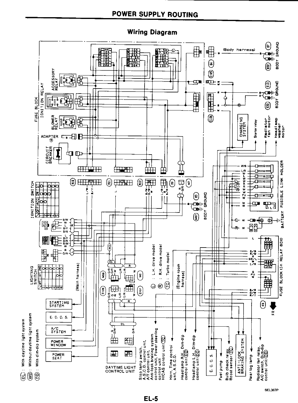
Power Supply Wiring Diagram For Nissan 300ZX
This circuit illustrates the power supply wiring diagram for the Nissan 300ZX, a sports car known as the Fairlady Z. Components include the lighting switch, ECCS, and fuse.
The power supply wiring diagram for the Nissan 300ZX is essential for understanding...
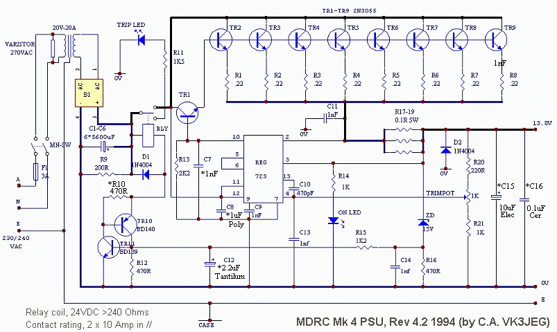
MDRC Mark 4 20 Amp Power Supply
The MDRC committee approached the author to take on the role of Electronic Components and Project Officer, which was accepted without hesitation. Upon assuming the position, it became evident that more time would be required than initially anticipated, primarily for...
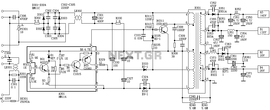
Sanyo 83P switching power supply circuit diagram
Oscillation: The positive terminal voltage of C310 is approximately 300V. The resistors R311 and R312 are connected to the switch BG311 at the B pole, while the B301 winding via the switching transformer (4) and (6) is connected to the...
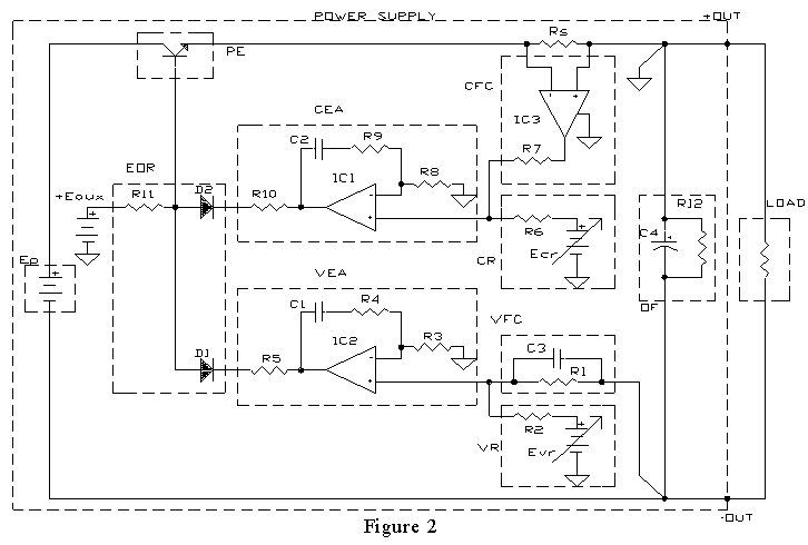
AMPLIFIER WITH FORCED EQUILIBRIUM ADAPTOR
Each power supply, whether linear or switching, operates in at least two modes: constant voltage (CV) and constant current (CC). The power supply can function in either mode, with the other serving as a protective mode for both the load...
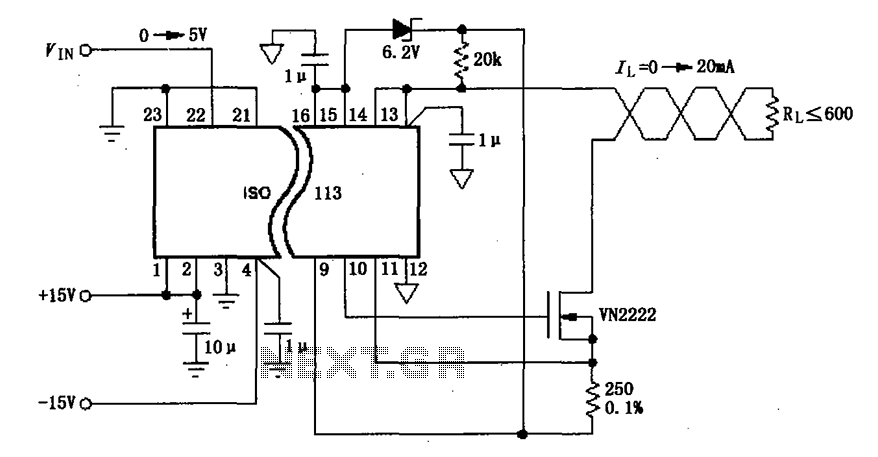
Constituted by the ISO113 0 ~ 20mA current loop isolation drive circuit diagram
The circuit depicted in the figure consists of an ISO113 current loop isolation drive circuit that operates with an input signal (VIN) to provide an isolated amplified output of 0 to 20 mA. This current is transmitted to the load...
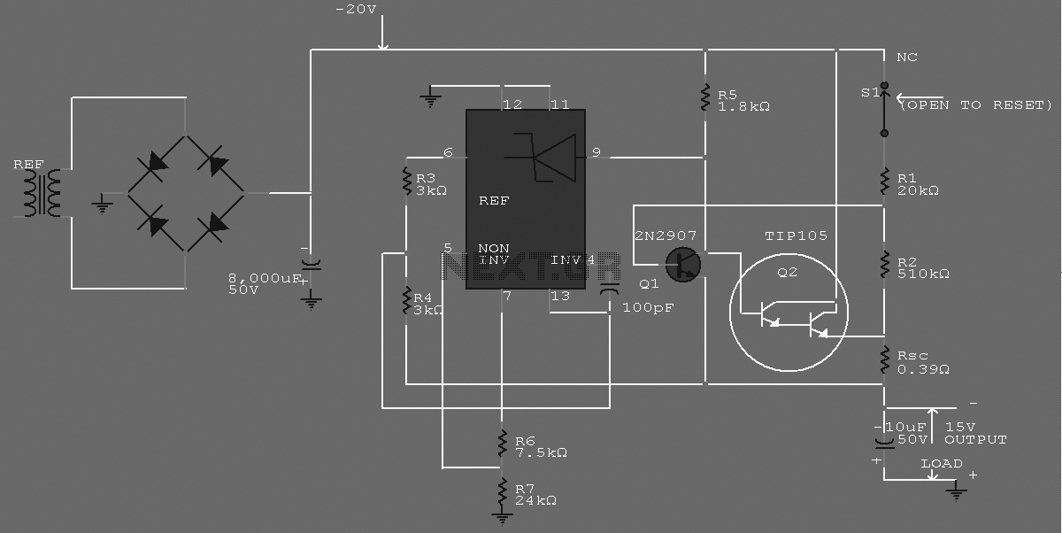
-15 V 1-A Regulated Power Supply
The supply receives -20 V from the rectifier/filter which is fed to the collector of the Darlington pnp pass transistor, a TIP105. The base drive to the TIP105 is supplied through resistor R5. The base of the TIP is driven...
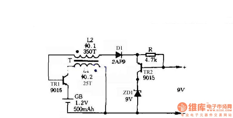
Self-control digital inverter power supply circuit diagram:1.2V rising to 9V
The circuit does not require a separate power switch or transformation to control the switches on the table. It offers advantages such as low power consumption, stability, reliability, and no impact on instrument accuracy. The transformer T in the circuit...

symmetric 12v to 5v converter
Symmetric 12V to 5V converter power supply. Refer to the designated page for an explanation regarding the associated circuit diagram.
The symmetric 12V to 5V converter power supply is designed to efficiently step down a 12V input voltage to a regulated...
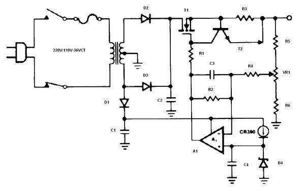
Battery charger or Power Supply 14 volt 4 ampere
The schematic diagram originates from a circuit designed as a battery charger/power supply with an output of 14V and a maximum current of 4A, utilizing the VN64GA MOSFET. This high-performance battery charger is specifically engineered for gelled electrolyte lead-acid batteries,...