


Dual-phase power switchover circuit schematic
#dual-phase
#switchover
#power line
#knife switch
#three-phase
#circuit schematic
#electrical
#voltage
#AC
#load management
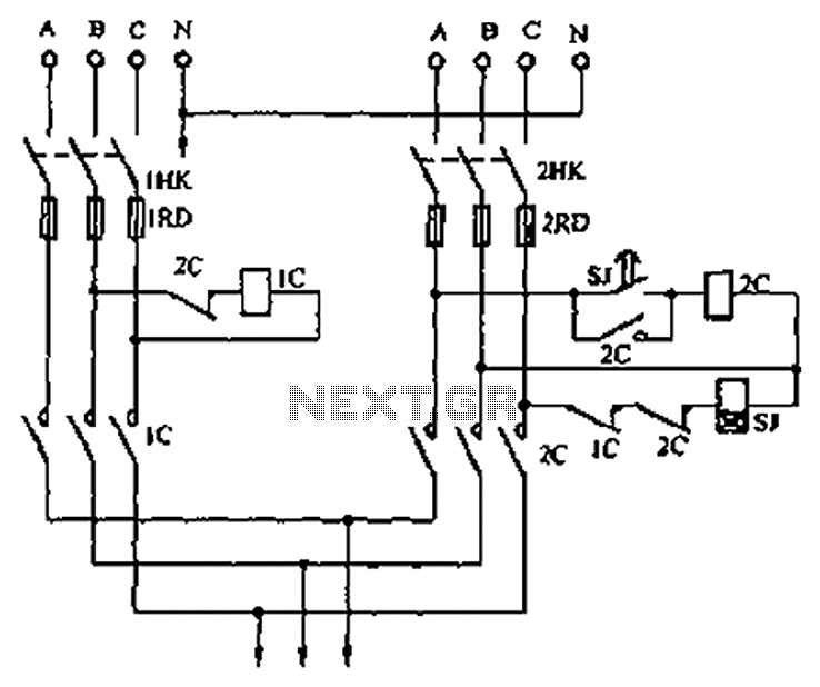
Description: A dual three-phase power line circuit is illustrated in the figure. When the knife switches 1HK and 2HK are closed simultaneously, the normally closed contact 1C disconnects the power supply to the time relay SJ, allowing power to reach the load. In the event of a power outage, contactor 1C releases, causing the normally closed contact to open. This action triggers the time relay SJ, which after a predetermined delay of several seconds, causes the normally open contact to close, energizing contactor 2C and enabling self-locking. As contactor 2C engages, it disconnects the power supply from the time delay relay on one side while simultaneously interrupting the power to the coil of contactor 1C, thereby halting power supply A and ensuring that power supply B remains operational. If power supply B experiences an outage after some time, the normally closed contact of 2C automatically switches, restoring power to the load from power supply A through contactor 1C. The choice of contactor should be based on the load size, and the time relay can be set for a delay of 0 to 60 seconds for AC operation.
The dual three-phase power line circuit operates as a failover mechanism to ensure continuous power supply to a load in the event of outages in either of the two power sources (A or B). The circuit utilizes two knife switches (1HK and 2HK) to control the flow of electricity. When both switches are closed, the circuit allows current to flow to the load through the normally closed contact 1C. This configuration is designed to provide redundancy; if one power source fails, the system can automatically switch to the other source without manual intervention.
The time relay SJ plays a critical role in this circuit, providing a delay that prevents rapid cycling between power sources during transient outages. The adjustable time delay (0 to 60 seconds) allows for flexibility based on the specific application and load requirements. Once the time relay is activated after a power failure, it transitions from its normally open state to closed, energizing contactor 2C. This contactor is responsible for maintaining power to the load while disconnecting the failed power source.
The self-locking feature of contactor 2C ensures that once it is energized, it remains engaged even if the triggering signal from the time relay is removed. This is crucial for maintaining stability in the power supply to the load. The circuit is designed with safety in mind; the interruption of the power supply to contactor 1C ensures that it does not inadvertently attempt to reconnect to a failed source, thereby protecting the system from potential damage.
In summary, this dual three-phase power line circuit effectively manages power supply redundancy through the use of strategic contacts and a time relay, ensuring reliable and continuous operation of the load under varying conditions. Proper selection of contactors based on load size is essential for optimal performance and reliability of the system. As shown in Figure is a dual three-phase power line circuit from the vote. When electricity at the same time closing the knife switch 1HK and 2HK, 1C normally closed contacts d isconnect the power supply SJ time relay. Power to the load. When A power outage for any reason, 1C contactor release, then IC normally closed, power relay SJ time line on the graph, time delay relay after a few seconds, so SJ delay normally open closes, 2C was electrically energized and self-locking. Since the 2C pull its normally closed one hand off-delay line drawing power, on the other hand double break 1C coil power supply circuit, so that the power to stop power supply A, B power supply to ensure normal power supply.
After working for some time if the B power outage, 2C normally closed automatically switched line circle 1C A power supply replaced. Contactor shall choose according to load size; time relay available 0 ~ 60S AC relay.
The dual three-phase power line circuit operates as a failover mechanism to ensure continuous power supply to a load in the event of outages in either of the two power sources (A or B). The circuit utilizes two knife switches (1HK and 2HK) to control the flow of electricity. When both switches are closed, the circuit allows current to flow to the load through the normally closed contact 1C. This configuration is designed to provide redundancy; if one power source fails, the system can automatically switch to the other source without manual intervention.
The time relay SJ plays a critical role in this circuit, providing a delay that prevents rapid cycling between power sources during transient outages. The adjustable time delay (0 to 60 seconds) allows for flexibility based on the specific application and load requirements. Once the time relay is activated after a power failure, it transitions from its normally open state to closed, energizing contactor 2C. This contactor is responsible for maintaining power to the load while disconnecting the failed power source.
The self-locking feature of contactor 2C ensures that once it is energized, it remains engaged even if the triggering signal from the time relay is removed. This is crucial for maintaining stability in the power supply to the load. The circuit is designed with safety in mind; the interruption of the power supply to contactor 1C ensures that it does not inadvertently attempt to reconnect to a failed source, thereby protecting the system from potential damage.
In summary, this dual three-phase power line circuit effectively manages power supply redundancy through the use of strategic contacts and a time relay, ensuring reliable and continuous operation of the load under varying conditions. Proper selection of contactors based on load size is essential for optimal performance and reliability of the system. As shown in Figure is a dual three-phase power line circuit from the vote. When electricity at the same time closing the knife switch 1HK and 2HK, 1C normally closed contacts d isconnect the power supply SJ time relay. Power to the load. When A power outage for any reason, 1C contactor release, then IC normally closed, power relay SJ time line on the graph, time delay relay after a few seconds, so SJ delay normally open closes, 2C was electrically energized and self-locking. Since the 2C pull its normally closed one hand off-delay line drawing power, on the other hand double break 1C coil power supply circuit, so that the power to stop power supply A, B power supply to ensure normal power supply.
After working for some time if the B power outage, 2C normally closed automatically switched line circle 1C A power supply replaced. Contactor shall choose according to load size; time relay available 0 ~ 60S AC relay.
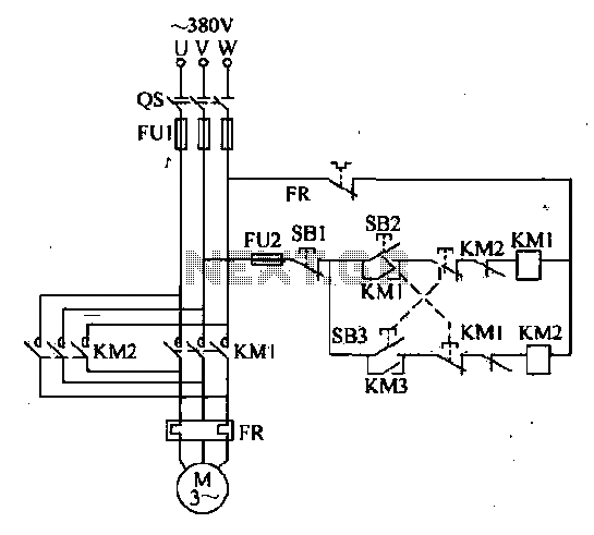
Double interlocking three-phase asynchronous motor control circuit
The forward and reverse dual interlock control circuit is based on the control circuit depicted in Figure 4-4, with an enhancement that incorporates a composite mechanical button interlock. The advantage of this circuit is that it allows the motor to...
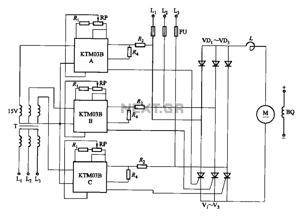
KTM03 type speed control for three-phase half-controlled rectifier circuit
Adjusting the phase potentiometer RP can change the conduction angle of each corresponding thyristor (V1-V). This adjustment alters the voltage applied across the load.
The circuit utilizes a phase control technique to manage the power delivered to a load by varying...
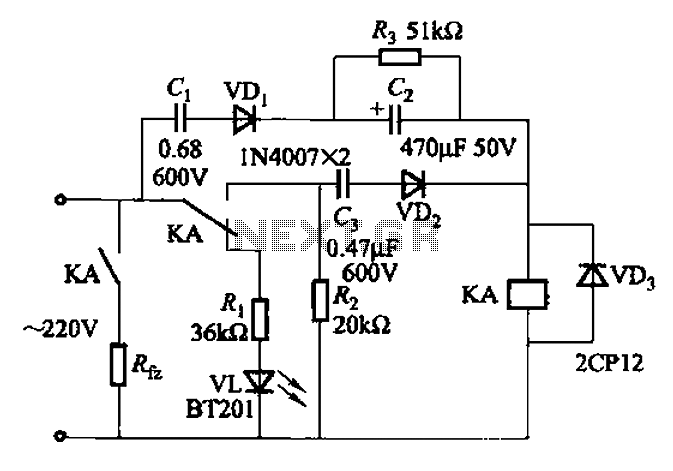
Simple AC short circuit protection
The AC power supply voltage is normal, and a relay is connected to the load (Rfz) circuit. In the event of a load short-circuit failure, the voltage across relay KA drops rapidly, causing KA to release and disconnect the load....
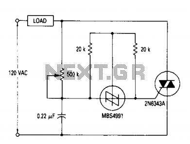
AC Lamp dimmer
A full range power controller suitable for lamp dimming and similar applications operates from a 120-volt, 60 Hz AC source and can control up to 1000 watts of power to incandescent bulbs. The power to the bulbs is varied by...
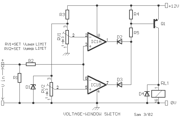
Voltage window switch
A voltage window switch is in practice the basic lower window limit of this circuit is roughly 3V and the upper limit is 9V. The window range can be extended by fitting a suitable range
Part List
R1-2=10Kohm D1=9V1/ 0.5W Zener IC1=TL072...
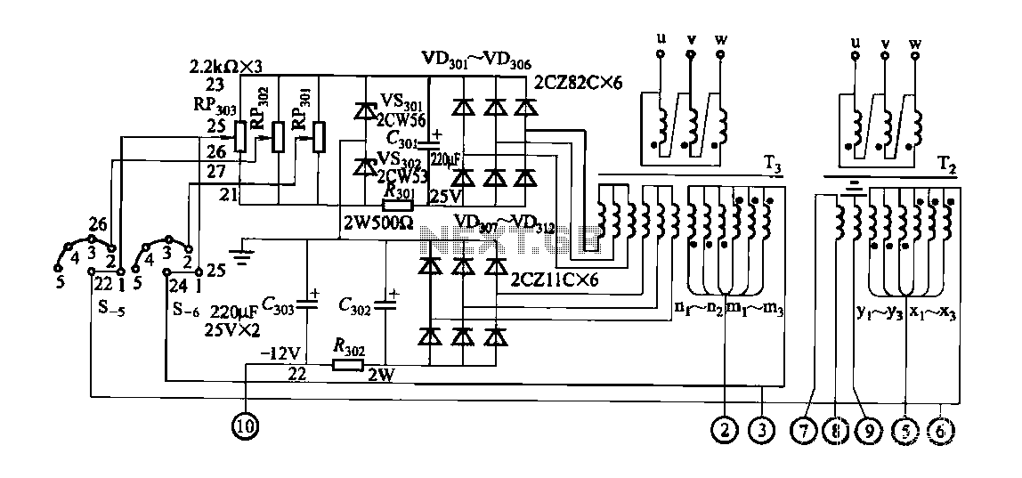
FGDF-3 three-phase low-temperature iron plating power supply circuit
FGDF-3 is a three-phase low-temperature iron plating power supply circuit, while the KGDF-3 is a single-phase low-temperature iron plating power supply device that encompasses all the characteristics of the power supply unit. This design allows for an even distribution of...
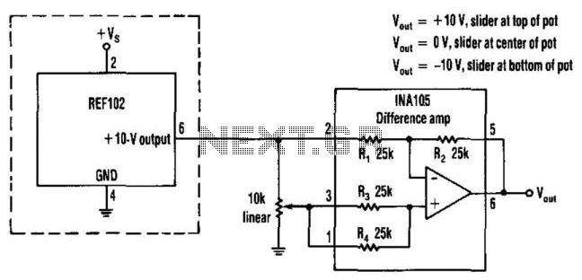
Positive And Negative Voltage Power Supply
This circuit provides a precision voltage source that can be adjusted to produce zero, positive, and negative voltages, eliminating the need to reverse connections on the power supply. It allows for achieving exactly 0 V without any offset. The circuit...
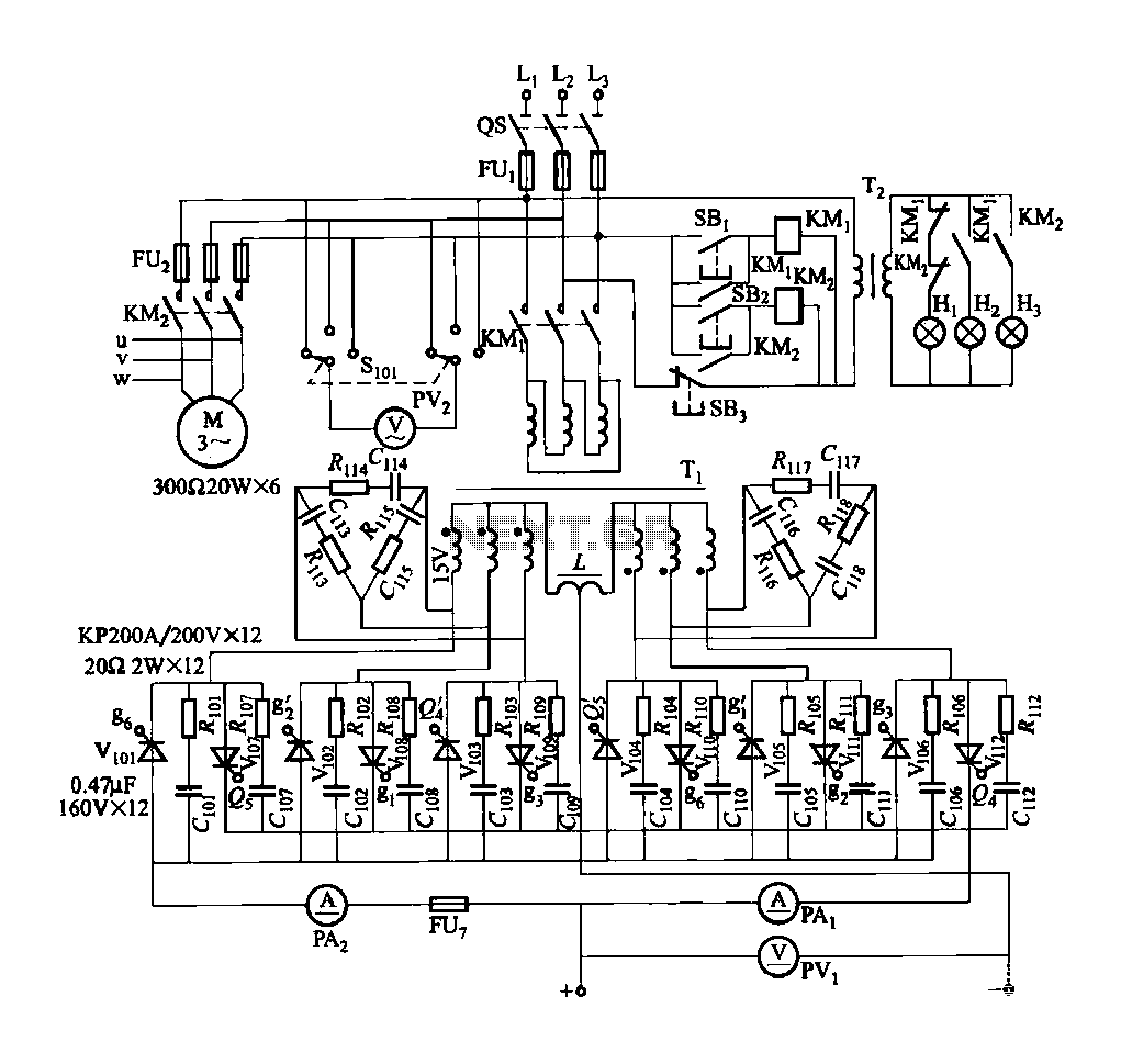
FGDF-3 three-phase low-temperature iron plating main circuit
FGDF-3 is a three-phase low-temperature iron plating main circuit, while the KGDF-3 represents a low-temperature iron plating power supply device that includes characteristics of a single-phase low-temperature iron plating power supply. This device utilizes a three-phase power grid to ensure...
Double interlocking three-phase asynchronous motor control circuit
The forward and reverse dual interlock control circuit is based on the control circuit depicted in Figure 4-4, with an enhancement that incorporates a composite mechanical button interlock. The advantage of this circuit is that it allows the motor to...