


East Shi IDS-2000F STB switching power supply circuit
#switching power supply
#AC input
#oscillation circuit
#output circuit
#East Shi IDS-2000F
#STB
#power conversion
#circuit design
#electronics
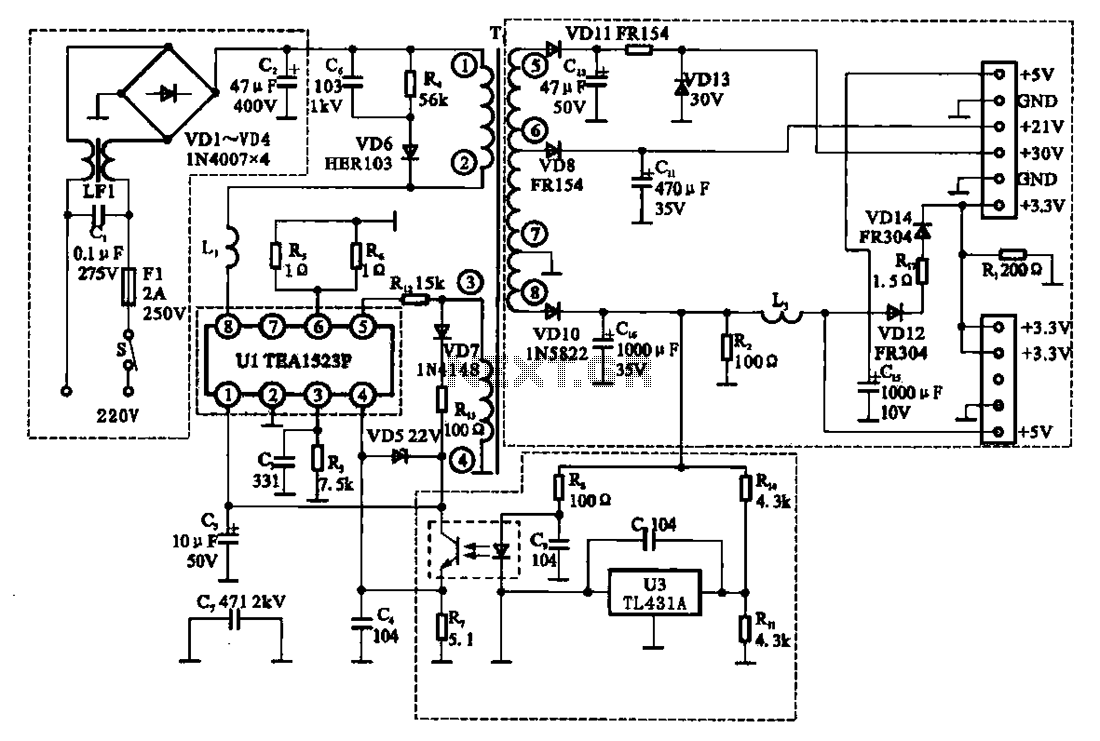
Description: The East Shi IDS-2000F STB switching power supply circuit primarily consists of an AC input circuit, a switching oscillation circuit, an output circuit, and a secondary steady voltage control circuit. The AC input circuit includes a switch (S), fuse (F1), mutual inductance filter (C1), inductor (LF1), and a bridge rectifier circuit (VD1-VD4). Its function is to filter the AC 220V input voltage and rectify it into a DC voltage of 300V, with C2 acting as the smoothing capacitor. The switching and oscillation control circuit is integrated within the TEA1523P (U1), which operates at 30V DC. The primary winding of transformer (T1) is connected to U1, allowing it to control the oscillation state via positive feedback. The secondary output circuit of transformer T1 provides multiple output voltage levels, including +5V, +21V, +3V, and +3.3V. The voltage regulator circuit is connected to the +5V output, where resistors R14 and R11 form a voltage divider. U3 serves as an error detection and amplifier, sending the error signal back to U1 through photoelectric coupling to control the oscillation output.
The East Shi IDS-2000F STB switching power supply circuit is a well-structured design that efficiently manages power conversion and regulation. The AC input circuit serves as the initial stage, where the AC voltage is filtered and converted to a high DC voltage. The inclusion of a fuse (F1) ensures protection against overloads, while the mutual inductance filter (C1) helps to eliminate high-frequency noise, enhancing the reliability of the power supply.
The switching oscillation circuit, utilizing the TEA1523P integrated circuit, is critical for maintaining the desired operational efficiency. This component generates the necessary switching signals to drive the transformer (T1), thus enabling the conversion of high-voltage DC into the required lower voltage outputs. The feedback mechanism, facilitated by the positive feedback winding, ensures that the oscillation frequency remains stable and responsive to load variations.
In the secondary output circuit, the multiple output voltages are achieved through the use of a switching transformer. Each output is rectified to provide stable voltage levels suitable for various applications, such as powering digital circuits, microcontrollers, and other electronic devices. The design incorporates voltage regulation to maintain output stability despite fluctuations in load or input voltage.
The voltage regulator circuit plays a vital role in ensuring that the +5V output remains consistent. The voltage divider formed by resistors R14 and R11 sets a reference level for the error amplifier (U3), which monitors the output voltage. Any deviation from the set point generates an error signal that is fed back to the TEA1523P (U1) via photoelectric coupling. This feedback loop allows for real-time adjustments to the oscillation output, ensuring that the power supply operates within specified voltage limits.
Overall, the East Shi IDS-2000F STB switching power supply circuit exemplifies an efficient and robust design, capable of delivering multiple output voltages with high reliability and stability.East Shi IDS-2000F STB switching power supply circuit East Shi IDS -2000F STB switching power supply circuit mainly by the AC input circuit, switching oscillation circuit, outp ut circuit and a secondary steady pressure control circuit and the like, as shown in Figure 2. 63. (1) AC input circuit AC input circuit is a switch S, fuse Fl, mutual inductance filter cl, LF1 and bridge rectifier circuit (VDI-VD4) and the like, its function is to filter the AC 220V input voltage and interference rectifier into a DC voltage of 300V, C2 to the smoothing capacitor. (2) switch and oscillation control circuit switches and the oscillation control circuit are integrated in Ul TEA1523P among the 30V DC via the switch of the primary winding of the transformer Ti O ~ to Ul foot power switch is integrated in Ul among the positive feedback winding ~ feet U1 provides power and positive feedback voltage to Ul access switch oscillation state.
(3) secondary output circuit switching transformer Ti attack multiple sets of output level, the rectifier output +5 V, + 21 V, + 3V and +3.V voltages. (4) regulator circuit voltage regulator circuit connected to the output of + 5V, Rl4, R11 constitute a voltage divider circuit, U3 to error detection and error amplifier, it will error signal by the photoelectric coupling of feedback to Ul feet, of Ul oscillation output controlled.
The East Shi IDS-2000F STB switching power supply circuit is a well-structured design that efficiently manages power conversion and regulation. The AC input circuit serves as the initial stage, where the AC voltage is filtered and converted to a high DC voltage. The inclusion of a fuse (F1) ensures protection against overloads, while the mutual inductance filter (C1) helps to eliminate high-frequency noise, enhancing the reliability of the power supply.
The switching oscillation circuit, utilizing the TEA1523P integrated circuit, is critical for maintaining the desired operational efficiency. This component generates the necessary switching signals to drive the transformer (T1), thus enabling the conversion of high-voltage DC into the required lower voltage outputs. The feedback mechanism, facilitated by the positive feedback winding, ensures that the oscillation frequency remains stable and responsive to load variations.
In the secondary output circuit, the multiple output voltages are achieved through the use of a switching transformer. Each output is rectified to provide stable voltage levels suitable for various applications, such as powering digital circuits, microcontrollers, and other electronic devices. The design incorporates voltage regulation to maintain output stability despite fluctuations in load or input voltage.
The voltage regulator circuit plays a vital role in ensuring that the +5V output remains consistent. The voltage divider formed by resistors R14 and R11 sets a reference level for the error amplifier (U3), which monitors the output voltage. Any deviation from the set point generates an error signal that is fed back to the TEA1523P (U1) via photoelectric coupling. This feedback loop allows for real-time adjustments to the oscillation output, ensuring that the power supply operates within specified voltage limits.
Overall, the East Shi IDS-2000F STB switching power supply circuit exemplifies an efficient and robust design, capable of delivering multiple output voltages with high reliability and stability.East Shi IDS-2000F STB switching power supply circuit East Shi IDS -2000F STB switching power supply circuit mainly by the AC input circuit, switching oscillation circuit, outp ut circuit and a secondary steady pressure control circuit and the like, as shown in Figure 2. 63. (1) AC input circuit AC input circuit is a switch S, fuse Fl, mutual inductance filter cl, LF1 and bridge rectifier circuit (VDI-VD4) and the like, its function is to filter the AC 220V input voltage and interference rectifier into a DC voltage of 300V, C2 to the smoothing capacitor. (2) switch and oscillation control circuit switches and the oscillation control circuit are integrated in Ul TEA1523P among the 30V DC via the switch of the primary winding of the transformer Ti O ~ to Ul foot power switch is integrated in Ul among the positive feedback winding ~ feet U1 provides power and positive feedback voltage to Ul access switch oscillation state.
(3) secondary output circuit switching transformer Ti attack multiple sets of output level, the rectifier output +5 V, + 21 V, + 3V and +3.V voltages. (4) regulator circuit voltage regulator circuit connected to the output of + 5V, Rl4, R11 constitute a voltage divider circuit, U3 to error detection and error amplifier, it will error signal by the photoelectric coupling of feedback to Ul feet, of Ul oscillation output controlled.
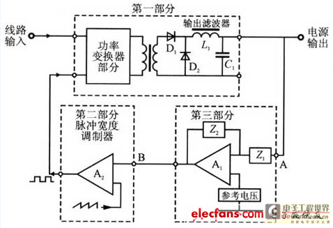
switching power supply stability cipher scheme
It is widely recognized that any closed-loop system has a unit gain in the noise temperature ratio. The phase shift within such a system varies with frequency, and at a phase shift of 360 degrees, stability in the closed-loop control...
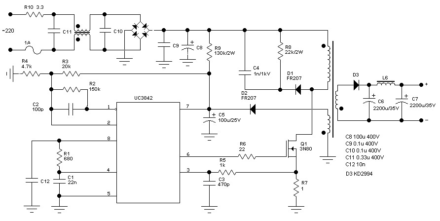
60 W Switching power supply
The schematic diagram originates from a 60 Watt Switching Power Supply. It details a power supply designed for a 70W stereo amplifier, utilizing the KA2S0880 chip, which encompasses all necessary components for constructing the primary section of the power supply....
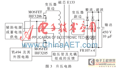
The multi-channel segregation with backup battery exports the switching power supply
With the rapid development of the social economy, the demand for electric energy continues to increase. In light of the diminishing availability of non-renewable energy sources, such as fossil fuels, many countries are recognizing the importance of energy conservation and...
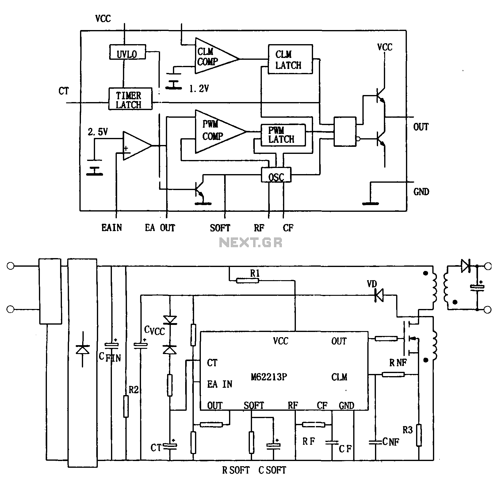
Switching power supply from the high-speed switching power supply controller M62213FP
Figure (a) illustrates a block diagram of the internal architecture of the M62213FP, which is a high-speed switching power supply controller. This device includes an oscillator, PWM comparator, error amplifier, output circuit, over-voltage protection, timing latch circuit, over-current protection circuit,...
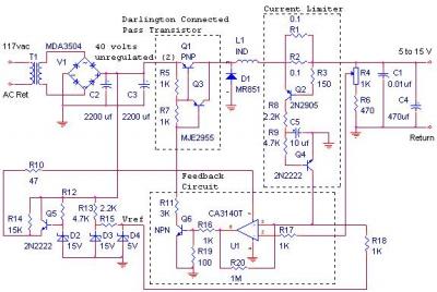
12V 10Amp MJ2955 Switching Power Supply
The switching power supply delivers 12 volts at a maximum current of 10 amps, utilizing a discrete transistor regulator with an operational amplifier functioning as a comparator within the feedback loop. The schematic does not depict the front panel power-on...
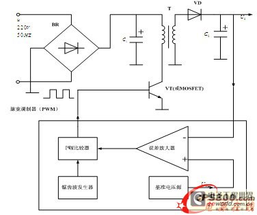
Design and simulation study of anti exciting type switching power supply of single-end
The energy conservation provided by switching power supplies has garnered significant attention due to its substantial economic benefits, leading to rapid adoption across various sectors. With the swift advancement in power technology, high-frequency operation has become a prevailing trend in...
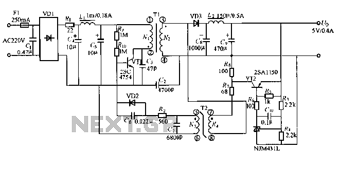
Output 5v / 0.4a small switching power supply circuit diagram
The output displays a 5V / 0.4A low-power switching power supply circuit, which can be utilized to create a transformer saturation soft-switching circuit.
This low-power switching power supply circuit is designed to provide a stable 5V output at a current of...
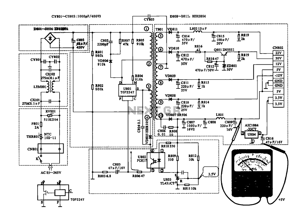
Coship CDVB3188V receiver switching power supply circuit
The Coship CDVB3188V receiver features a switching power supply circuit similar to the CDVB3188C model. The circuit includes several key components: an AC input circuit, an anti-jamming filter circuit, a complete flow filter circuit, and a switching oscillation circuit. (1)...
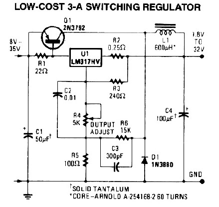
3A Switching Power Supply
The following diagram illustrates a 50W offline switching power supply circuit design. The circuit is powered by a MOSFET, specifically the BUZ80A/IXTP4N8 for a 220V AC voltage input and the GE IRF823 for a 110V AC input voltage. The output...