


Electrolytic Capacitor Reforming Circuit
#electrolytic capacitor
#capacitor reforming
#leakage current
#power supply
#capacitor maintenance
#storage
#high voltage
#DC
#circuit protection
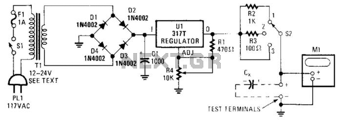
Description: Sometimes electrolytic capacitors that are stored for a period may exhibit high leakage currents. Before utilizing these capacitors, it may be necessary to reform them. This power supply can be employed for the reforming process. Adjust resistor R4 according to the capacitor's rated voltage and set switch S2 to position X. When meter Ml indicates the rated voltage, the reforming process is complete. For larger capacitors, use position 2 initially, and then switch to position 3 after the reforming has commenced. Transformer TX can be any transformer rated between 12 to 24 Vac at approximately 1A.
The described circuit functions as a reforming power supply specifically designed for electrolytic capacitors that have been stored for extended periods. These capacitors often develop high leakage currents, which can compromise their performance in circuits. The reforming process involves applying a controlled voltage to the capacitors to restore their functionality and reduce leakage.
The circuit includes a variable resistor, R4, which allows for the adjustment of the output voltage to match the rated voltage of the capacitor being reformed. The switch S2 is utilized to select the appropriate mode for the reforming process. In position X, the circuit applies a gradual voltage increase to the capacitor. This controlled application is crucial to prevent damage to the capacitor and to ensure that it can safely handle its rated voltage.
The inclusion of meter Ml is essential for monitoring the voltage applied to the capacitor. Once the meter indicates that the rated voltage has been reached, it signifies that the reforming process is complete, and the capacitor can be safely utilized in its intended application.
For larger electrolytic capacitors, the circuit provides flexibility by allowing the user to initially set S2 to position 2. This setting enables a lower voltage application to start the reforming process gently. After a certain duration, the user can switch to position 3 to continue the reforming at a higher voltage, ensuring effective restoration of the capacitor's performance.
The transformer TX is a key component in this circuit, providing the necessary AC voltage for the reforming process. A transformer rated between 12 to 24 Vac at approximately 1A is suitable for this application, ensuring that the circuit can deliver the required power without exceeding the ratings of the components involved. Proper implementation of this power supply circuit will effectively restore the functionality of stored electrolytic capacitors, making them safe for use in electronic applications. Sometimes electrolytic capacitors that are stored for some time will exhibit high leakage currents . Before placing these in service, the capacitors might need to be reformed. This power supply can be used for reforming. Adjust R4 for the capacitor"s rated voltage and set S2 in position X. When Ml indicates the rated voltage, reforming is complete. For large capacitors, use position 2, and then position 3 after reforming starts. TX can be any transformer with a rating of 12 to 24 Vac at about 1A.
The described circuit functions as a reforming power supply specifically designed for electrolytic capacitors that have been stored for extended periods. These capacitors often develop high leakage currents, which can compromise their performance in circuits. The reforming process involves applying a controlled voltage to the capacitors to restore their functionality and reduce leakage.
The circuit includes a variable resistor, R4, which allows for the adjustment of the output voltage to match the rated voltage of the capacitor being reformed. The switch S2 is utilized to select the appropriate mode for the reforming process. In position X, the circuit applies a gradual voltage increase to the capacitor. This controlled application is crucial to prevent damage to the capacitor and to ensure that it can safely handle its rated voltage.
The inclusion of meter Ml is essential for monitoring the voltage applied to the capacitor. Once the meter indicates that the rated voltage has been reached, it signifies that the reforming process is complete, and the capacitor can be safely utilized in its intended application.
For larger electrolytic capacitors, the circuit provides flexibility by allowing the user to initially set S2 to position 2. This setting enables a lower voltage application to start the reforming process gently. After a certain duration, the user can switch to position 3 to continue the reforming at a higher voltage, ensuring effective restoration of the capacitor's performance.
The transformer TX is a key component in this circuit, providing the necessary AC voltage for the reforming process. A transformer rated between 12 to 24 Vac at approximately 1A is suitable for this application, ensuring that the circuit can deliver the required power without exceeding the ratings of the components involved. Proper implementation of this power supply circuit will effectively restore the functionality of stored electrolytic capacitors, making them safe for use in electronic applications. Sometimes electrolytic capacitors that are stored for some time will exhibit high leakage currents . Before placing these in service, the capacitors might need to be reformed. This power supply can be used for reforming. Adjust R4 for the capacitor"s rated voltage and set S2 in position X. When Ml indicates the rated voltage, reforming is complete. For large capacitors, use position 2, and then position 3 after reforming starts. TX can be any transformer with a rating of 12 to 24 Vac at about 1A.
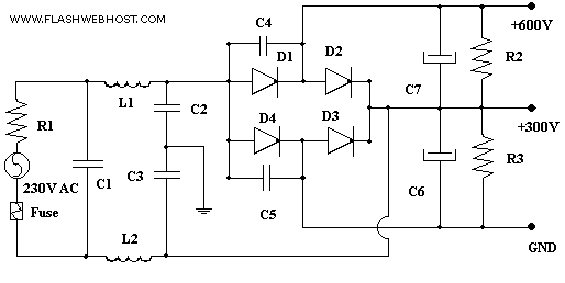
600 VOLTS POWER SUPPLY FOR QRO
Amateur Radio Transmitters using valves such as 807 or 1625 works well with a plate voltage between 600V to 700 Volts. The circuit described here is a full wave voltage doubler. The output voltage is twice the input voltage. For...

symmetric 12v to 5v converter
Symmetric 12V to 5V converter power supply. Refer to the designated page for an explanation regarding the associated circuit diagram.
The symmetric 12V to 5V converter power supply is designed to efficiently step down a 12V input voltage to a regulated...
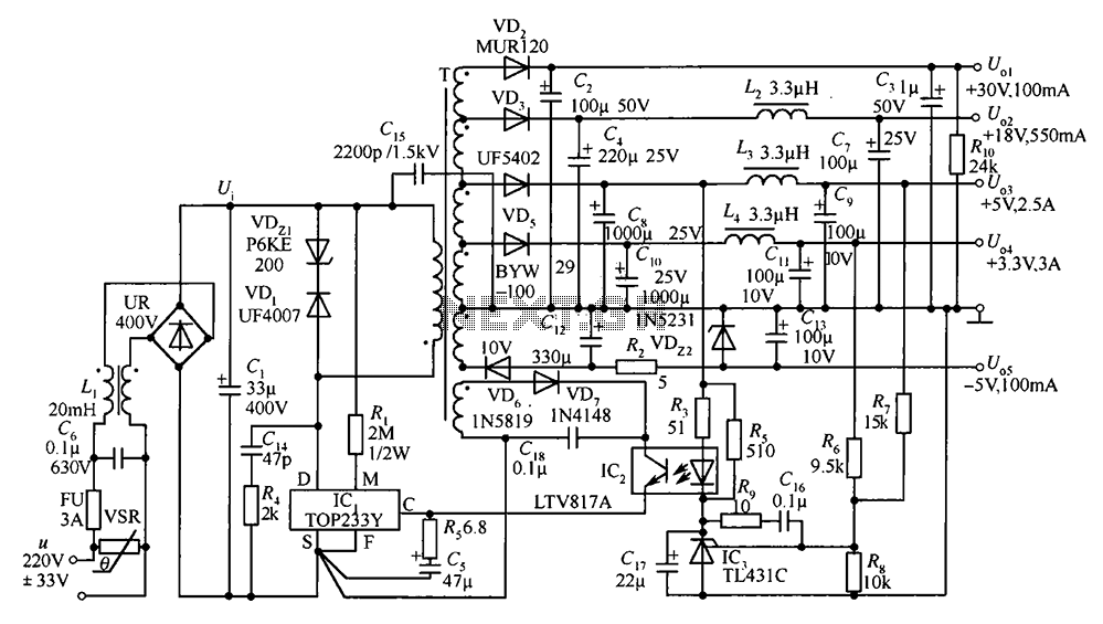
35W switching power supply circuit having a set-top box output of 5
A 35W switching power supply circuit designed for a set-top box output is depicted in Figure 5. It features five distinct voltage outputs: Uo1 (+30V, 100mA), Uo2 (+18V, 550mA), Uo3 (+5V, 2.5A), Uo4 (+3.3V, 3A), and Uo5 (-5V, 100mA). The...
electricity
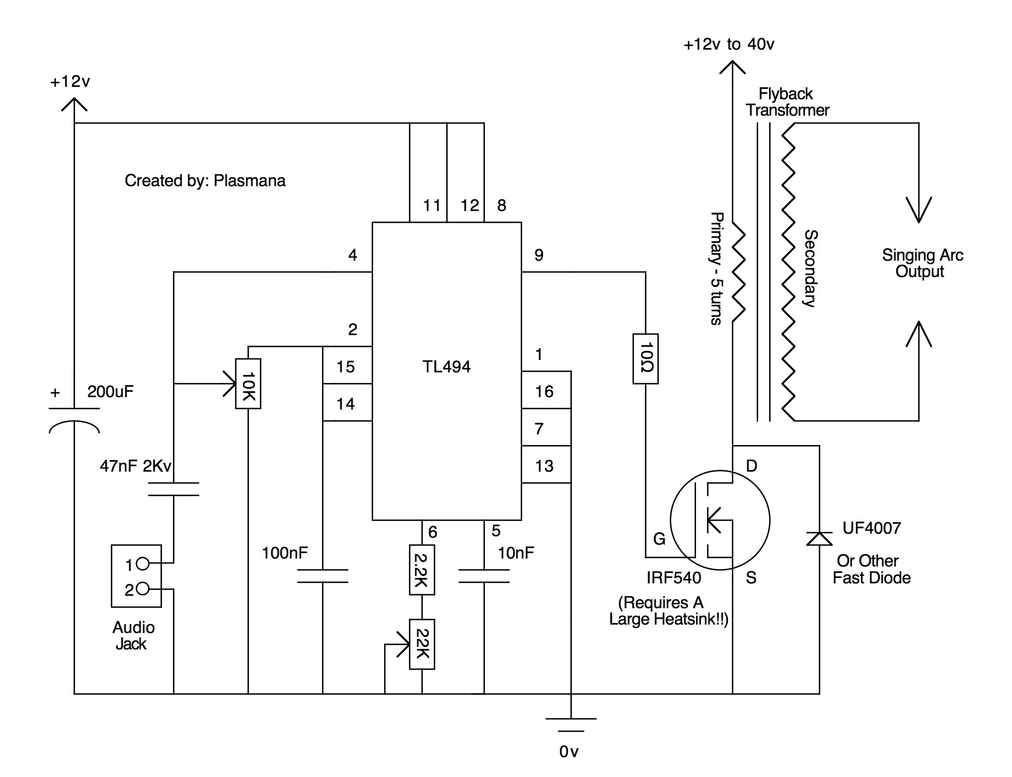
According to the datasheet, they will switch about 160 kW at up to 10 kV (7.2 kV typical). Unfortunately, this is insufficient for the quarter shrinker; however, a miniature ring flipper may be in development. A presentation will be held...
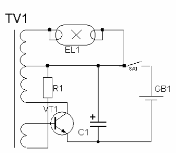
high voltage power supply circuit for fluorescent light
High-voltage power supply circuit for fluorescent light power supply. Refer to that page for an explanation of the related circuit diagram.
The high-voltage power supply circuit designed for fluorescent lights typically consists of several key components that work together to convert...
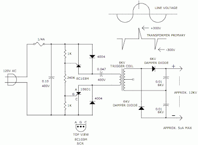
12KV High Voltage Generator
The hobby circuit described utilizes a unique method to generate approximately 12,000 volts with a current of about 5 microamperes. It employs two silicon-controlled rectifiers (SCRs) that form two pulse generator circuits. These SCRs discharge a 0.047 microfarad, 400-volt capacitor...
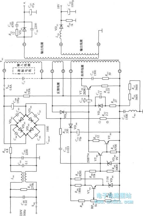
High voltage switching stabilized voltage supply circuit
A high voltage switching stabilized voltage supply circuit is illustrated in the diagram. This is the switching power supply for an 80P type color television. It utilizes auto-excitation and a PWM circuit. The output is isolated from the power system,...
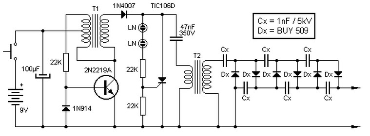
9V to 13.5kV Inverter Circuit Schematic Diagram
This high voltage source consists of an inverter built around a transistor that generates pulses of 150V. These pulses are supplied to an inverter made of a thyristor and a capacitor, which is connected in series with transformer T2. The...
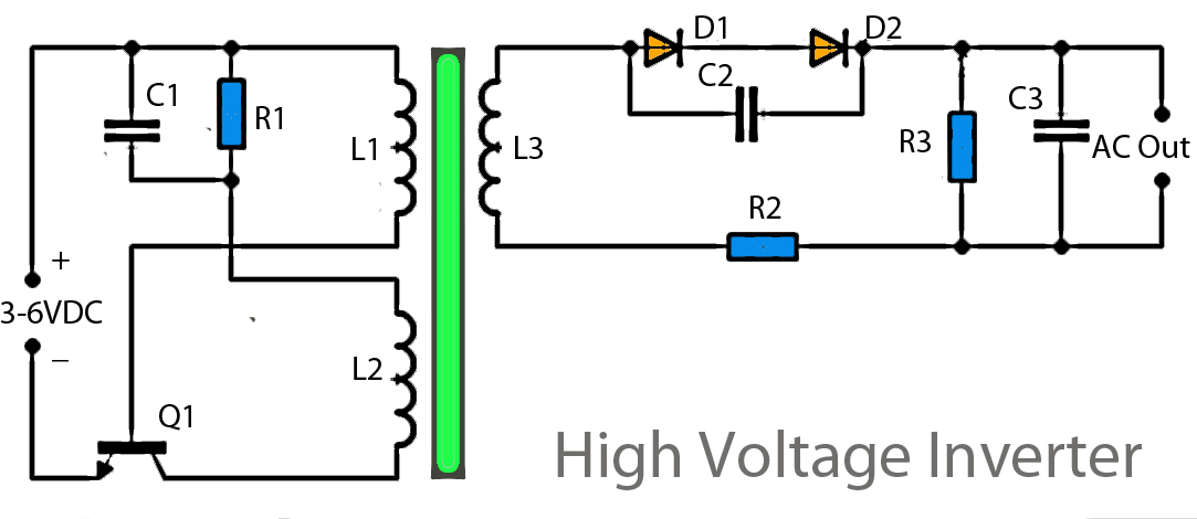
high-voltage-inverter-circuit-diagram.html
This inverter circuit operates using a transistor and transformer, along with other components, to elevate the voltage. The input supply voltage ranges from 3V to 6V DC, which is then converted to a high voltage AC output. However, the output...