


EMR4.0 application circuit
#EMR4.0
#single power supply
#6V-10V
#power filtering
#noise reduction
#9V power supply
#LC filter
#quiescent state
#voltage regulation
#power management
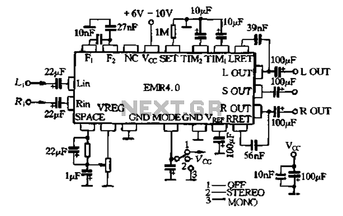
Description: The EMR 4.0 operates with a single power supply ranging from 6V to 10V, with an optimal supply voltage of 9V. It requires effective power filtering to minimize noise, particularly when there is no signal input. The quiescent current is 11 mA. The EMR 4.0 allows a maximum input signal level of 1V. A crossover in the general assembly can cause signal cut-off if the input is too small, which may diminish processing performance and reduce the circuit's dynamic range. The circuit gain is set to 1, and the output must be connected to a buffer amplifier with a certain gain. It is recommended to connect the circuit with volume and tone controls beforehand to enhance the signal-to-noise ratio and lower distortion.
The EMR 4.0 circuit is designed to function optimally within specified voltage and current parameters. The power supply should be stable, with noise filtering implemented to ensure high fidelity during operation. The use of a 9V supply is ideal, as it balances performance and efficiency. The circuit's quiescent current of 11 mA indicates a relatively low power consumption, making it suitable for battery-operated applications.
To accommodate varying input signal levels, the EMR 4.0 is engineered to handle a maximum input of 1V. If the input signal falls below this threshold, it may lead to unwanted crossover distortion, particularly in the general assembly stage. This distortion can adversely affect the overall processing capabilities of the circuit, leading to a diminished dynamic range. Therefore, careful attention must be given to the input signal levels to ensure optimal circuit performance.
The output stage of the EMR 4.0 must incorporate a buffer amplifier to maintain signal integrity. This buffer amplifies the output without introducing additional noise, ensuring that the final output is clean and precise. Additionally, the integration of volume and tone controls prior to the output stage is crucial. These controls allow for adjustments that enhance the signal-to-noise ratio, thus further reducing distortion and improving audio quality.
In summary, the EMR 4.0 is a robust circuit that requires careful consideration of power supply, input levels, and output buffering to achieve high-performance audio processing. Proper implementation of these elements is essential for maximizing the circuit's potential and ensuring high-quality signal reproduction.EMR 4 0 with a single power supply (6V ~ 10V) power supply, power supply when 9V best. It requires better power filtering, noise lower opening the lc no signal input quiescent current of 11 deletion gas. RESEARCH contented 4-0 allow maximum input signal level is 1V, crossing over the General Assembly cause cut, too small will reduce the processing performance and reduces the dynamic range of the circuit gain o 1, which surround output must be connected to a certain gain buffer amplifier. Circuits should be connected with the volume and tone circuit before, in order to improve the signal to noise ratio and lower distortion o Figure 9-54 EMR 4.0 is the application circuit o
The EMR 4.0 circuit is designed to function optimally within specified voltage and current parameters. The power supply should be stable, with noise filtering implemented to ensure high fidelity during operation. The use of a 9V supply is ideal, as it balances performance and efficiency. The circuit's quiescent current of 11 mA indicates a relatively low power consumption, making it suitable for battery-operated applications.
To accommodate varying input signal levels, the EMR 4.0 is engineered to handle a maximum input of 1V. If the input signal falls below this threshold, it may lead to unwanted crossover distortion, particularly in the general assembly stage. This distortion can adversely affect the overall processing capabilities of the circuit, leading to a diminished dynamic range. Therefore, careful attention must be given to the input signal levels to ensure optimal circuit performance.
The output stage of the EMR 4.0 must incorporate a buffer amplifier to maintain signal integrity. This buffer amplifies the output without introducing additional noise, ensuring that the final output is clean and precise. Additionally, the integration of volume and tone controls prior to the output stage is crucial. These controls allow for adjustments that enhance the signal-to-noise ratio, thus further reducing distortion and improving audio quality.
In summary, the EMR 4.0 is a robust circuit that requires careful consideration of power supply, input levels, and output buffering to achieve high-performance audio processing. Proper implementation of these elements is essential for maximizing the circuit's potential and ensuring high-quality signal reproduction.EMR 4 0 with a single power supply (6V ~ 10V) power supply, power supply when 9V best. It requires better power filtering, noise lower opening the lc no signal input quiescent current of 11 deletion gas. RESEARCH contented 4-0 allow maximum input signal level is 1V, crossing over the General Assembly cause cut, too small will reduce the processing performance and reduces the dynamic range of the circuit gain o 1, which surround output must be connected to a certain gain buffer amplifier. Circuits should be connected with the volume and tone circuit before, in order to improve the signal to noise ratio and lower distortion o Figure 9-54 EMR 4.0 is the application circuit o
Power Management
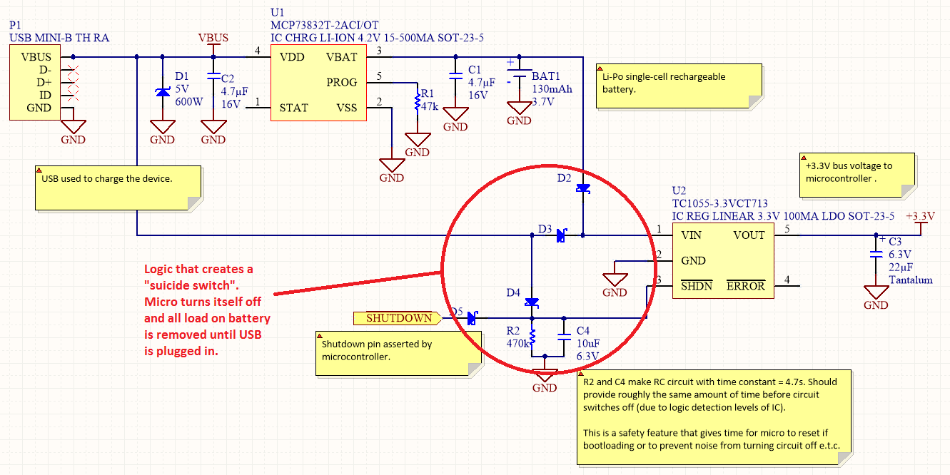
Overview Disabling Sections of a Circuit The "Suicide Switch" Overview Power management is a significant design consideration for battery-powered devices.
Power management is a crucial aspect of circuit design, particularly in battery-powered applications where energy efficiency directly impacts the operational lifespan...
How to extend the battery life of your microcontroller based design
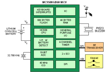
Battery-powered devices, such as electric toothbrushes, shavers, cell phones, PDAs, MP3 players, and remote controls, are integral to daily life. Consequently, power management has become a critical consideration for embedded designers. Microcontrollers (MCUs) provide various methods for managing power requirements...
Power Path Management Battery Charger
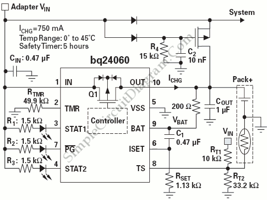
Powering the system is required by many applications while charging the battery simultaneously. Interaction between the system and charger may result in a...
Power management in electronic systems is critical, particularly in applications that necessitate simultaneous operation and battery charging. This...
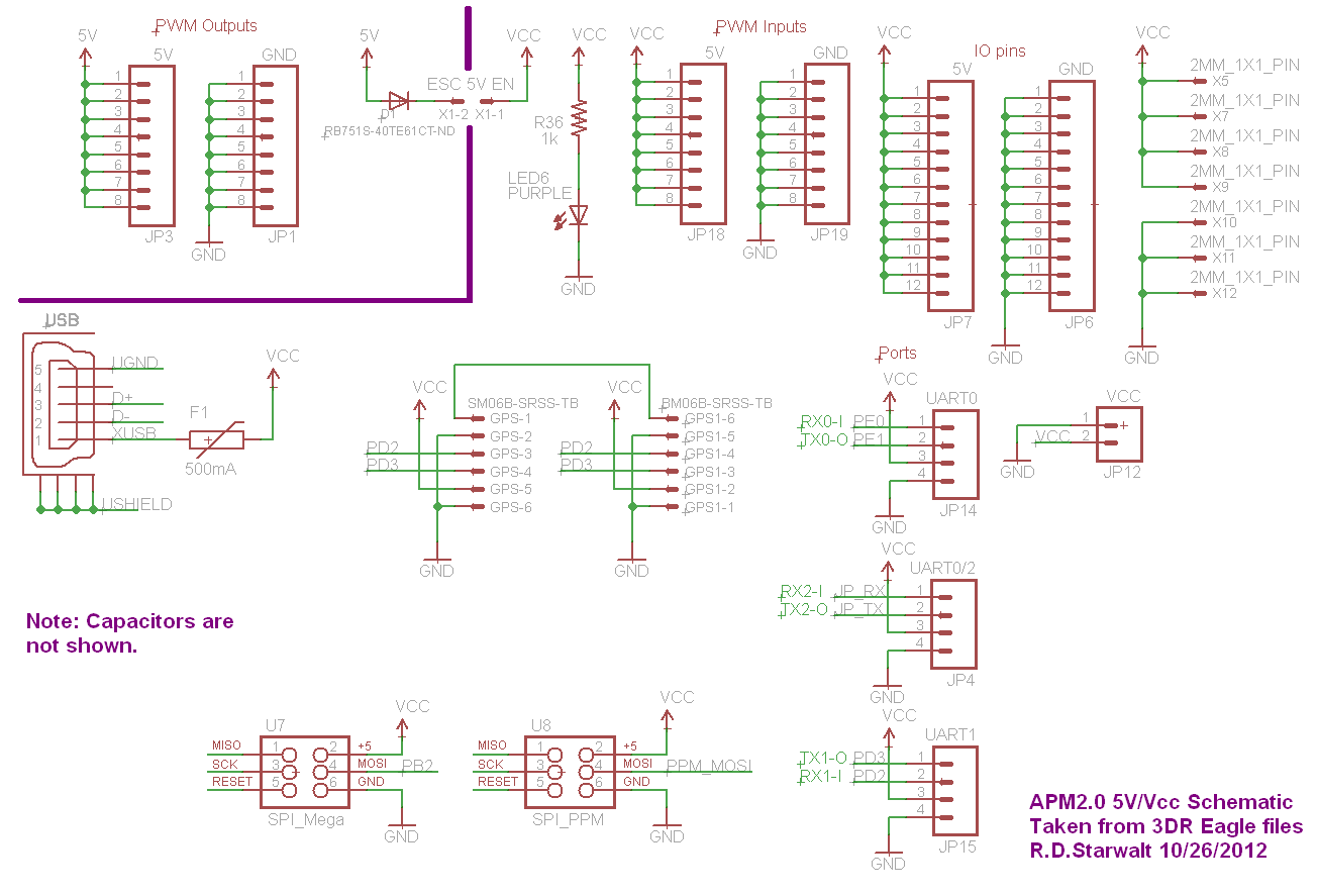
APM2.0 5V/Vcc Schematic
The PWM Output section has been separated into the upper left corner, delineated by a heavy purple line that is bridged by jumper JP1 on the APM2.0. This design choice highlights that diode D1 allows current to pass through JP1,...
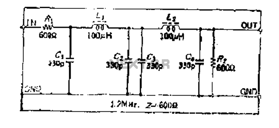
Simple design with a constant K-type high-frequency low-pass LC filter
Due to the amplifier's frequency characteristics and the impact of parasitic capacitance, designing an active filter that operates effectively at hundreds of kilohertz is quite challenging. Additionally, since the circuit consists of a low-pass filter with a large coil inductance...

A Power Management Interface Circuit For Telecom Hot Swap With Local Dc/dc Conve
New cellular phones have incorporated high-resolution cameras that require bright illumination of the surrounding area to achieve high-quality pictures. Traditional xenon-filled photo flashes cannot be used due to the limited space available in cellular phone cameras. Instead, design engineers utilize...
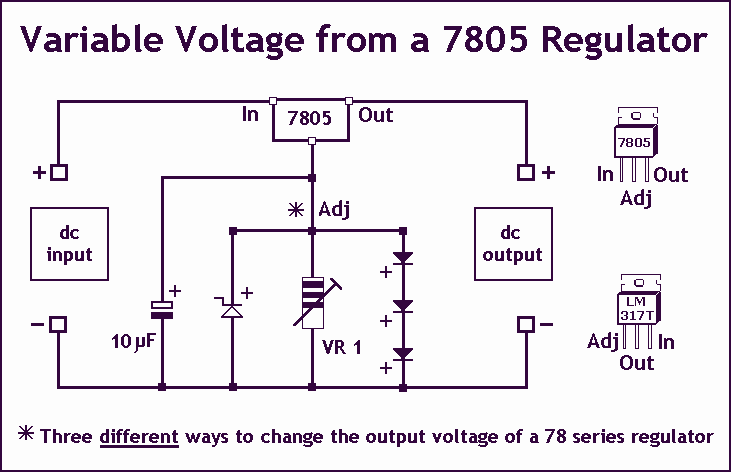
Variable Voltage Regulation
Controlling the output voltage from a regulator can be made variable in three ways:
1. Using a fixed reference zener diode to increase the output by the value of the zener
2. A variable resistor for variable output, note that...
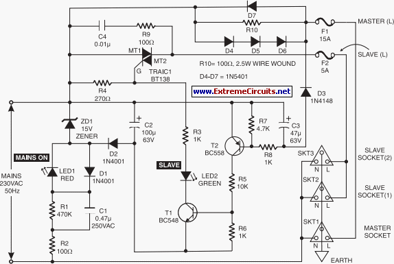
Mains Manager
It is common to forget to turn off peripherals such as monitors, scanners, and printers when shutting down a PC. Typically, these devices are connected to a four-way trailing socket, which is plugged into a wall outlet. If this outlet...
Voltage Regulators
Until Willow Garage was acquired, there was work as a Web Robotics Engineer. This title reflects a role as a full-stack engineer focused on real-time, distributed robot control. Notable projects include an XML-RPC server and client for Node.js, a deprecated...