


High-frequency active power factor correction of switching power supply of large-screen color TV
#power factor correction
#switching power supply
#high-frequency
#PFC
#large-screen TV
#energy conservation
#electrical equipment
#200-300W
#active PFC
#color TV
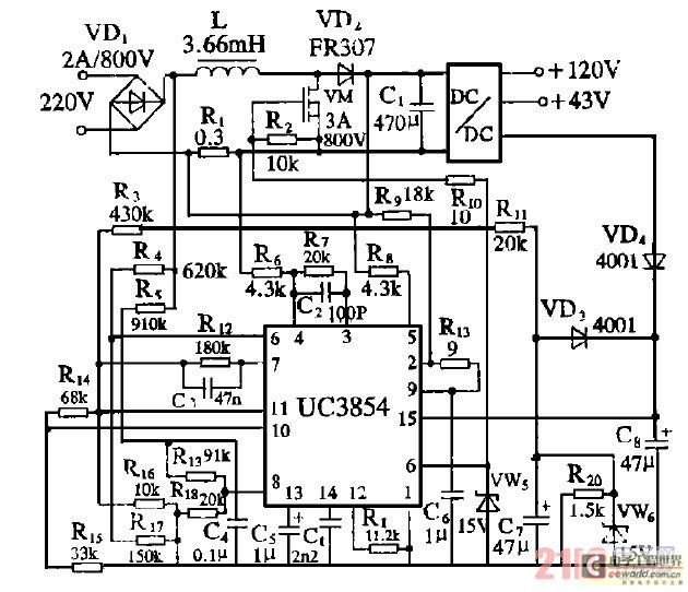
Description: Improve the power factor (PF) to enhance energy conservation in electrical equipment. With advancements in electronic technology, high-frequency active power factor correction (PFC) technology has been increasingly applied across various power systems. The switching power supply of large-screen color televisions typically ranges from 200 to 300W. The conventional electric switching power supply, when coupled with a smoothing circuit, tends to generate significant harmonic currents, resulting in a low power factor, generally between 0.65 and 0.85. To enhance the electrical characteristics of large-screen color televisions, high-frequency active PFC technology has been incorporated into the design, improving the PF characteristics. This can be defined as the product of the distortion factor and the phase shift factor. In switching power supplies, the cosine value generally approaches 1, indicating minimal phase shift, yet the harmonic current remains substantial, leading to a small distortion factor. Low PF in electrical equipment can result in several issues: serious harmonic current pollution of the electrical grid, interference with other electrical devices, increased average input current necessitating larger circuit specifications and protective devices, increased power supply capacity, and heightened load on central lines, compromising safety. High-frequency active PFC employs PWM signals that adjust based on the voltage and current changes in the electrical grid. By controlling the high-frequency electronic switch, it regulates the inductance (L), improving the current waveform. The multiplier controls the PWM signal, allowing the input current to approximate a sine wave, achieving a PF greater than or equal to 0.99. Figure 1 illustrates the functional block diagram of the PFC. Typically, an uncontrolled full-bridge rectifying circuit is combined with an electrolytic capacitor smoothing circuit in large-screen color televisions directly connected to the switching power supply. Figure 2 depicts the configuration of this circuit. Resistor R2 limits the inrush current; once the filtering electrolytic capacitor is fully charged, relay K opens, breaking the connection to R2. The input voltage and current waveforms of the circuit are shown in Figure 3. It can be observed from Figure 3 that current is drawn from the electrical grid only when the line-side voltage exceeds the electrolytic capacitor voltage, resulting in a significant harmonic current composition. The calculated PF is typically low, between 0.65 and 0.85. For a switching power supply of approximately 300W in large-screen color televisions, about one-third to one-fifth of this power is reactive. By implementing active PFC technology to achieve a PF of 0.99 or higher, significant energy savings of 60 to 100W can be realized. The design incorporates a more active PFC circuit for the switching power supply in large-screen color televisions, utilizing a press-fit type circuit. The control circuit employs average current control, with the UC3854 chip, as illustrated in Figure 4. The operational principle involves generating control pulses from the UC3854 based on output voltage, output current, and load current. This controls the gas switching tube, continuously monitoring and adjusting the current in L to align with the sinusoidal voltage of the unidirectional input after commutation, maintaining proportionality. Additionally, to achieve output adjustment of the direct current voltage, a multiplier is utilized for regulation.Improve the power factor PF Use a energy-conserving important factor of electrical equipment. With the development of electric electron technology, high-frequency active power factor correction PFC Technology has already been more and more applied to various power widely. The power of switching power supply of large-screen color TV is among 200 300W, the original color electric switching power supply is adopted and commutated ordinarily with the smoothing circuit, its composition of harmonic current is large, the power is low because of the number value, it is generally 0. 65~ 0. 85. In order to improve the electrical properties of electric festival of large screen color, we adopted high-frequency active PFC technology in the design, have improved PF characteristic.
It is obvious, can also be defined as the product of distortion factor and phase shift factor. To switching power supply, cos generally approaches 1, namely phase shift is not big, but the harmonic current is serious, the distortion factor is small. The ones that use the electrical equipment PF low, apt to cause the following to endanger: Harmonic current pollute electric wire netting seriously, interfere with, spend the electrical equipment while being other; The mean value of input current is heavy, need to increase the specifications of circuit and protective device; The capacity increases to supply power, strengthen the preceding stage apparatus such as voltage transformer Quota; Have increased the load of central line greatly, has reduced safety performance.
High-frequency active PFC is PWM signal emerges according to the voltage, electric current and change that supports of the electric wire netting, ones that control the high-frequency electronic beam switch to be turned on, can play a role in regulating the inductance L. Improve the electric current waveform, utilize the multiplier to control PWM signal, can make the input current of the electric wire netting basically a sine wave, enable approach 1 Namely is greater than 0.
99. Fig. 1 shows the functional block diagram of PFC. Generally adopt the uncontrolled rectifying circuit of the full-bridge to add the smoothing circuit of electrolytic capacitor in the Off-The-Shelf large-screen color TV directly by the switching power supply. Fig. 2 shows the form of this circuit. R2 is used to limit the current-on contact, after inputting the filtering electrolytic capacitor to fully charge, K close, it is connected that R2 is broken, the input voltage of exchange, electric current waveform of the circuit are shown in Fig.
3. Can be seen by Fig. 3, only when the amplitude of voltage on line side is higher than the voltage of electrolytic capacitor, the electric current is just taken from the electric wire netting out, therefore the current harmonics composition is very great. It is very low to calculate such corrugate, generally in 0. 65~ 0. Between 85. The input power of switching power supply of large-screen color TV, about 300W, among them 1/ 3 ~ 1/ 5 It is the reactive power, if adopt active PFC technology to make its greater than or equal to 0.
99, Namely 1, so can economize on electricity 60100W is very considerable. Design by circuits more active than PFC of switching power supply on large-screen color TV by the press-fit type circuit risesing, its controlling circuit adopts the control mode of the average current, the chip adopts UC3854, the concrete circuit is shown in Fig. 4. Its operating principle is: According to output voltage, output current and load current, produced the control impulse from UC3854, control the gas switching tube to be turned on, continuous monitoring and regulating the electric current in L, make it follow the sinusoidal voltage of unidirectional input after commutating, and proportional to it; In addition, in order to realize to exporting the adjustment of the direct-current volts, utilize the multiplier and adjust and
It is obvious, can also be defined as the product of distortion factor and phase shift factor. To switching power supply, cos generally approaches 1, namely phase shift is not big, but the harmonic current is serious, the distortion factor is small. The ones that use the electrical equipment PF low, apt to cause the following to endanger: Harmonic current pollute electric wire netting seriously, interfere with, spend the electrical equipment while being other; The mean value of input current is heavy, need to increase the specifications of circuit and protective device; The capacity increases to supply power, strengthen the preceding stage apparatus such as voltage transformer Quota; Have increased the load of central line greatly, has reduced safety performance.
High-frequency active PFC is PWM signal emerges according to the voltage, electric current and change that supports of the electric wire netting, ones that control the high-frequency electronic beam switch to be turned on, can play a role in regulating the inductance L. Improve the electric current waveform, utilize the multiplier to control PWM signal, can make the input current of the electric wire netting basically a sine wave, enable approach 1 Namely is greater than 0.
99. Fig. 1 shows the functional block diagram of PFC. Generally adopt the uncontrolled rectifying circuit of the full-bridge to add the smoothing circuit of electrolytic capacitor in the Off-The-Shelf large-screen color TV directly by the switching power supply. Fig. 2 shows the form of this circuit. R2 is used to limit the current-on contact, after inputting the filtering electrolytic capacitor to fully charge, K close, it is connected that R2 is broken, the input voltage of exchange, electric current waveform of the circuit are shown in Fig.
3. Can be seen by Fig. 3, only when the amplitude of voltage on line side is higher than the voltage of electrolytic capacitor, the electric current is just taken from the electric wire netting out, therefore the current harmonics composition is very great. It is very low to calculate such corrugate, generally in 0. 65~ 0. Between 85. The input power of switching power supply of large-screen color TV, about 300W, among them 1/ 3 ~ 1/ 5 It is the reactive power, if adopt active PFC technology to make its greater than or equal to 0.
99, Namely 1, so can economize on electricity 60100W is very considerable. Design by circuits more active than PFC of switching power supply on large-screen color TV by the press-fit type circuit risesing, its controlling circuit adopts the control mode of the average current, the chip adopts UC3854, the concrete circuit is shown in Fig. 4. Its operating principle is: According to output voltage, output current and load current, produced the control impulse from UC3854, control the gas switching tube to be turned on, continuous monitoring and regulating the electric current in L, make it follow the sinusoidal voltage of unidirectional input after commutating, and proportional to it; In addition, in order to realize to exporting the adjustment of the direct-current volts, utilize the multiplier and adjust and
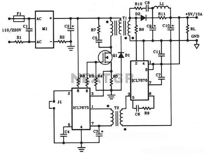
5V/10A 50W Offline Switching Power Supply
The following diagram illustrates a 50W offline switching power supply circuit design. This circuit is powered by a MOSFET, specifically the BUZ80A/IXTP4N8 for a 220V AC voltage input and the GE IRF823 for a 110V AC voltage input. The output...
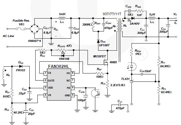
FAN302HL 5 volt switching power supply circuit design electronic project
A simple 5-volt switching power supply electronic circuit project can be designed using the FAN302HL, a highly integrated PWM controller integrated circuit. This IC provides several features that enhance the performance of general flyback converters. The constant-current control of the...
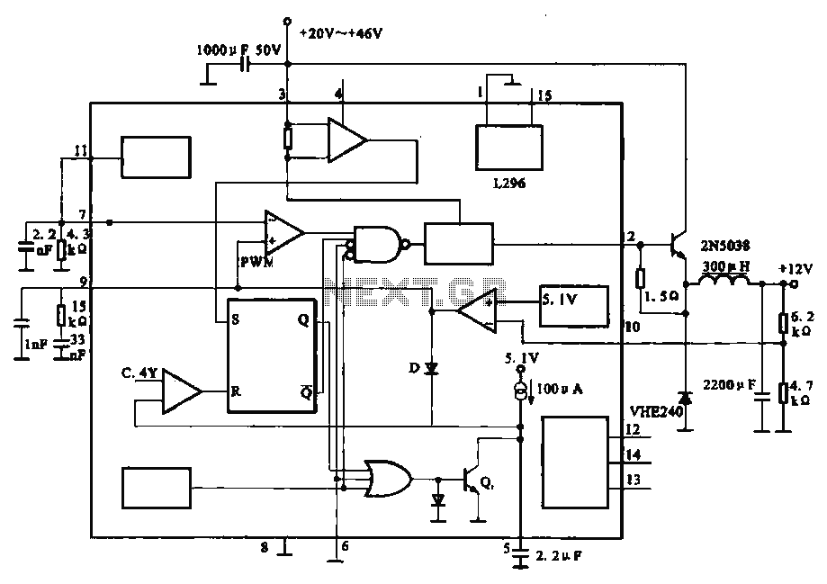
Output 12V-10A power circuit
The circuit outputs 12V at 10A and utilizes a high-current switching power supply design based on the L296 component. This configuration allows for an output current of up to 10A, and the entire circuit is compact with minimal component usage.
The...
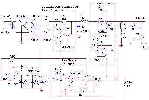
12 Volt, 10 Amp Switching Power Supply
The switching power supply, shown in the schematic, provides 12 volts, at 10 amps, maximum, using a discrete transistor regulator with an op-amp functioning as a comparator in the feedback circuit. The supply was constructed in 1984 and is variable...
12 Volt, 10 Amp Switching Power Supply
The switching power supply, shown in the schematic, provides 12 volts, at 10 amps, maximum, using a discrete transistor regulator with an op-amp functioning as a comparator in the feedback circuit. The supply was constructed in 1984 and is variable...
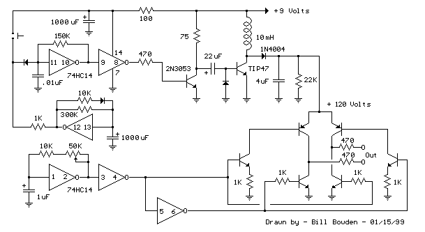
Switching Supply In Telephone Ring Generator
The telephone ring generator illustrated below produces the necessary high voltage using a simple switching mode power supply (SMPS) that incorporates a CMOS Schmitt Trigger square wave oscillator, a 10 mH inductor, a high voltage switching transistor (such as TIP47...
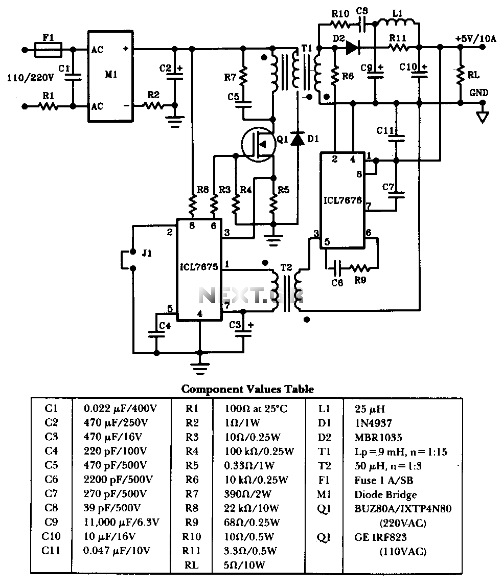
50W-offline-switching-power-supply
The schematic illustrates a 50W power supply providing a 5V, 10A output. It operates as a flyback converter in continuous mode. The circuit incorporates both primary and secondary side controllers, offering full protection against fault conditions such as overcurrent. Once...
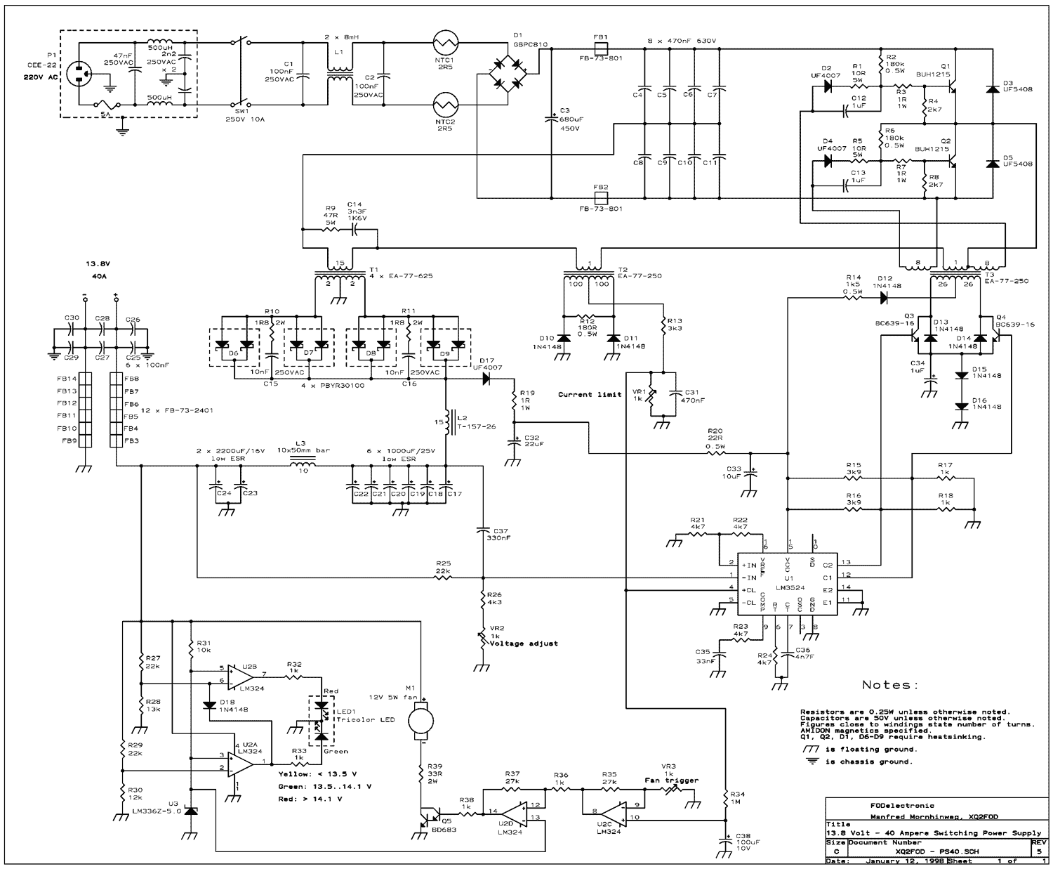
12V 40A Switching Power Supply
The present trend is to use ever higher frequencies. But by doing so it becomes more difficult to filter out the RF noise inevitably generated by the switching. So I decided to stay at a low switching frequency of only...
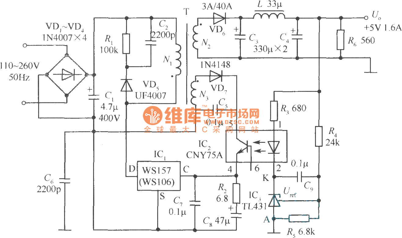
+5V 1.6A precision switching power supply circuit
The +5V, 1.6A precision switching power supply circuit is depicted in the figure. This circuit utilizes a photoelectric coupler (CNY75A) and an adjustable precision parallel regulator (TIA31). R3 serves as the current limiting resistor, while R4 and R5 function as...