


How To Build A Simple Current Limiting Bench Power Supply
#bench power supply
#variable voltage
#current limiting
#PSU
#voltage regulator
#electronics project
#DIY power supply
#1-amp
#3v to 24v
#soak-test
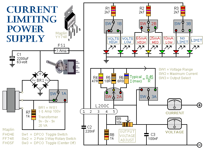
Description: This is a 1-amp variable-voltage power supply unit (PSU) that adjusts the output voltage from approximately 3V to 24V. It features a current limiting option, which is particularly useful for initial power-ups or soak-testing equipment. SW3 acts as the on/off switch and allows the user to select between the output with current limiting and the one without. SW2 offers three different current limit settings, which can be adjusted as necessary. The limits are determined by resistors R4, R5, and R6, set at 10mA, 25mA, and 65mA, respectively, but can be customized. If the load attempts to draw a current exceeding the selected limit, the output voltage will drop, and the voltmeter will indicate excessive load. The housing should be adequately ventilated, and the heatsink is a folded aluminum strip approximately 2mm thick, 18cm long, and 6cm tall. SW1 allows selection between 3V to 12V and 3V to 24V outputs, reducing the power dissipation required by the heatsink at lower output voltages. The front panel drawing serves mainly as a wiring diagram, allowing for user-defined layouts. The pin spacing of the L200C may not be compatible with stripboard but can be adjusted for fit. Due to the potentially low values of the limiting resistors, a few ohms between the wafer switch contacts may significantly affect operation. If the current limits decrease over time, a spray cleaner can be used on the switch.
This variable-voltage power supply unit (PSU) is designed to provide adjustable output voltage and current limiting capabilities, making it suitable for a range of electronic projects and testing scenarios. The primary component, the L200C voltage regulator, is capable of delivering a maximum output current of 1 ampere, with a voltage range adjustable from approximately 3 volts to 24 volts.
The PSU incorporates a user-friendly interface with multiple switches. SW3 serves as the main power switch, enabling the user to turn the device on or off. Additionally, it allows for the selection of output modes: one with current limiting and one without. This feature is critical for protecting sensitive components during initial tests or when applying power to new circuits.
SW2 is utilized to select one of three current limits, defined by the resistors R4, R5, and R6. These resistors are strategically chosen to set maximum current outputs at 10mA, 25mA, and 65mA, respectively. This flexibility allows users to adapt the power supply to various applications, ensuring that components are not subjected to excessive current that could lead to damage. The current limiting feature operates by reducing the output voltage if the load attempts to draw more current than the preset limit, thus providing a clear indication of excessive load conditions via the voltmeter.
The design emphasizes thermal management, featuring a heatsink made from folded aluminum, which is crucial for dissipating heat generated during operation. The dimensions of the heatsink (2mm thick, 18cm long, and 6cm tall) are optimized to balance effective cooling with the overall size of the PSU. Ventilation of the housing is essential to maintain safe operating temperatures.
SW1 allows the user to select between two output voltage ranges: 3V to 12V and 3V to 24V. This selection not only simplifies the operation but also minimizes the power that needs to be dissipated by the heatsink when operating at lower voltages, enhancing the efficiency of the power supply.
The construction of the PSU is adaptable, with the front panel layout serving primarily as a wiring diagram. Users are encouraged to modify the layout according to their preferences, allowing for customization to meet specific project requirements. The L200C's pin spacing may require adjustments for compatibility with stripboard, but with careful modification, it can be integrated effectively.
Finally, it is important to maintain the integrity of the current limiting feature. If the limits appear to decrease over time, application of a spray cleaner to the switch contacts can help restore functionality, ensuring reliable operation of the power supply unit over time.This is a 1-amp variable-voltage PSU. It adjusts from about 3v to 24v: and has the added feature that you can limit the maximum output current. This is invaluable when (for example) you power-up a project for the first time or soak-test a piece of equipment.
SW3 is the on/off switch. It also lets you choose between the output with the current limi t and the one without. SW2 provides a selection of three different limits. You can increase or decrease this number if you wish. The limits are fixed by R4, R5 & R6. They are set at 10mA, 25mA & 65mA respectively; but you can choose whatever limits you like. If you try to draw a current above the limit you`ve selected, the output voltage will fall. Thus, the voltmeter indicates when the load on the output is excessive. The housing should be well ventilated. The heatsink is a folded strip of aluminium about 2mm thick, 18cm long and 6cm tall. SW1 allows you to choose between the (3v to 12v) and (3v to 24v) outputs. This reduces the power the heatsink has to dissipate when the output voltage is low. The drawing of the front panel is intended mainly as a wiring diagram - you can choose your own layout. The pin spacing of the L200C doesn`t suit the stripboard; but with a little persuasion it can be made to fit.
Since the limiting resistors may have a relatively low value, a few ohms between the contacts of the wafer-switch will have a significant effect. If (with time) you find that the limits have fallen, use a spray-cleaner on the switch.
This variable-voltage power supply unit (PSU) is designed to provide adjustable output voltage and current limiting capabilities, making it suitable for a range of electronic projects and testing scenarios. The primary component, the L200C voltage regulator, is capable of delivering a maximum output current of 1 ampere, with a voltage range adjustable from approximately 3 volts to 24 volts.
The PSU incorporates a user-friendly interface with multiple switches. SW3 serves as the main power switch, enabling the user to turn the device on or off. Additionally, it allows for the selection of output modes: one with current limiting and one without. This feature is critical for protecting sensitive components during initial tests or when applying power to new circuits.
SW2 is utilized to select one of three current limits, defined by the resistors R4, R5, and R6. These resistors are strategically chosen to set maximum current outputs at 10mA, 25mA, and 65mA, respectively. This flexibility allows users to adapt the power supply to various applications, ensuring that components are not subjected to excessive current that could lead to damage. The current limiting feature operates by reducing the output voltage if the load attempts to draw more current than the preset limit, thus providing a clear indication of excessive load conditions via the voltmeter.
The design emphasizes thermal management, featuring a heatsink made from folded aluminum, which is crucial for dissipating heat generated during operation. The dimensions of the heatsink (2mm thick, 18cm long, and 6cm tall) are optimized to balance effective cooling with the overall size of the PSU. Ventilation of the housing is essential to maintain safe operating temperatures.
SW1 allows the user to select between two output voltage ranges: 3V to 12V and 3V to 24V. This selection not only simplifies the operation but also minimizes the power that needs to be dissipated by the heatsink when operating at lower voltages, enhancing the efficiency of the power supply.
The construction of the PSU is adaptable, with the front panel layout serving primarily as a wiring diagram. Users are encouraged to modify the layout according to their preferences, allowing for customization to meet specific project requirements. The L200C's pin spacing may require adjustments for compatibility with stripboard, but with careful modification, it can be integrated effectively.
Finally, it is important to maintain the integrity of the current limiting feature. If the limits appear to decrease over time, application of a spray cleaner to the switch contacts can help restore functionality, ensuring reliable operation of the power supply unit over time.This is a 1-amp variable-voltage PSU. It adjusts from about 3v to 24v: and has the added feature that you can limit the maximum output current. This is invaluable when (for example) you power-up a project for the first time or soak-test a piece of equipment.
SW3 is the on/off switch. It also lets you choose between the output with the current limi t and the one without. SW2 provides a selection of three different limits. You can increase or decrease this number if you wish. The limits are fixed by R4, R5 & R6. They are set at 10mA, 25mA & 65mA respectively; but you can choose whatever limits you like. If you try to draw a current above the limit you`ve selected, the output voltage will fall. Thus, the voltmeter indicates when the load on the output is excessive. The housing should be well ventilated. The heatsink is a folded strip of aluminium about 2mm thick, 18cm long and 6cm tall. SW1 allows you to choose between the (3v to 12v) and (3v to 24v) outputs. This reduces the power the heatsink has to dissipate when the output voltage is low. The drawing of the front panel is intended mainly as a wiring diagram - you can choose your own layout. The pin spacing of the L200C doesn`t suit the stripboard; but with a little persuasion it can be made to fit.
Since the limiting resistors may have a relatively low value, a few ohms between the contacts of the wafer-switch will have a significant effect. If (with time) you find that the limits have fallen, use a spray-cleaner on the switch.
Voltage Regulator
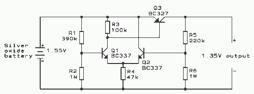
This regulator is suitable for devices that need up to 1mA. For higher output current, the resistors would have to be scaled down in reverse proportion to the peak current expected. With the resistor values shown, the regulator draws a...
STABILIZER POWER SUPPLY 0-30 VDC CIRCUIT
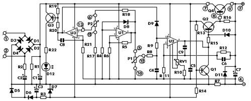
This is an aerial current power supply with a continuously adjustable stabilized output ranging from 0 to 30VDC. The circuit also incorporates an electronic current limiter that effectively controls the output current from a few milliamperes (2 mA) to a...
Practical-current-limiting-coil-driver
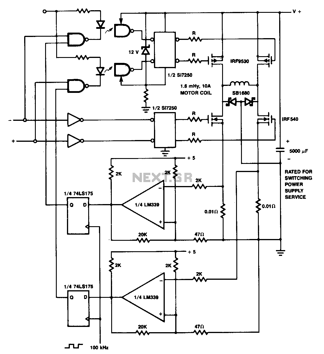
The p-channel devices are deactivated by current sensors when the coil current reaches 10 A. The operation resembles that of a switching-type power supply. Additionally, Schottky diodes and resistors are utilized for spike protection.
In this circuit, p-channel MOSFETs serve as...
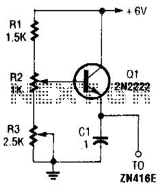
+1.5V Supply For Zn416E circuits
This regulator can be used with a +6-V source to supply the ZN416E low-voltage TRF radio receiver IC with the necessary +1.5 V. R3 sets the output voltage.
The circuit utilizes a voltage regulator designed to convert a +6 V input...

Current Limiting Power Supply
This is a 1-amp variable-voltage power supply unit (PSU) that can adjust output voltage from approximately 3V to 24V. It features a maximum output current limit, which is particularly useful when powering up a project for the first time or...
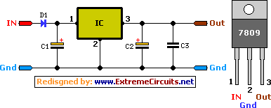
9 Volt 2 Ampere DC Power Supply Circuit
This circuit primarily relies on a voltage regulator. The 7809 voltage regulator can provide a continuous output of up to 2 amps while ensuring a low noise and highly regulated supply. Although the circuit can function without additional components, a...
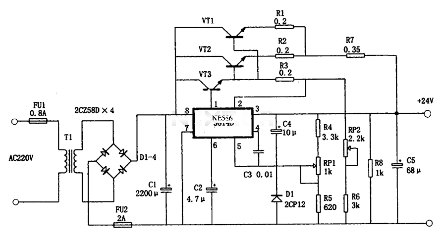
5G14D + 24V 1.9A power supply
The circuit illustrated in the figure is a +24V, 1.9A power supply design. It employs the 5G14D domestic integrated voltage regulator as the core component, supported by three external power transistors. While the 5G14D voltage regulator has a rated current...
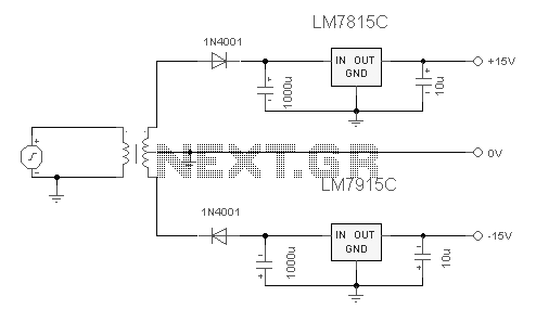
Dual Regulated Power Supply
The 7815 regulates the positive supply, while the 7915 regulates the negative supply. The transformer should have a primary rating of 240/220 volts for Europe or 120 volts for North America. The center-tapped secondary coil should be rated approximately 18...
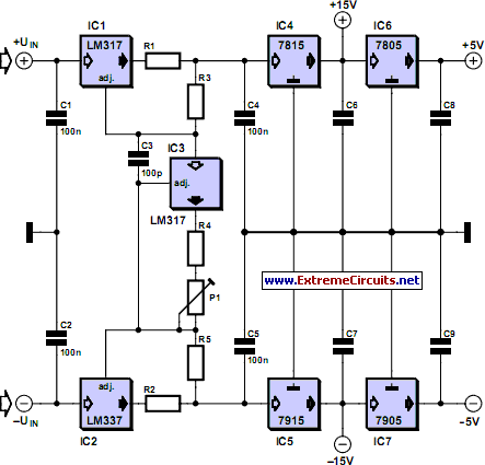
Adjustable Current Limit For Dual Power Supply circuit
This current-limiting circuit, illustrated in this example as part of a small bench power supply, could theoretically be utilized alongside any dual-rail current source. The section of the circuit to the left of the diagram restricts the input current to...