


Improve power supply rejection ratio PSR circuit diagram ISO124
#PSR
#ISO124
#MC78L05
#MC79L05
#DCP011515
#voltage regulator
#noise reduction
#signal integrity
#circuit design
#power management
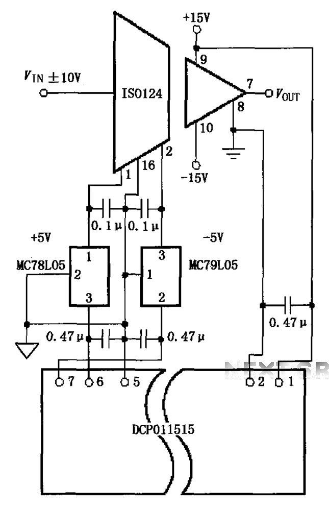
Description: The circuit depicted in the figure includes the ISO124 and MC78L05 components, along with an external regulator, MC79L05, and the DCP011515, which collectively enhance the power supply rejection ratio (PSR) of the circuit. The input signal, VIN (maximum swing of 10V), is processed through the ISO124 for isolation. The isolated DC/DC converter, DCP011515, is responsible for supplying isolated power, and two three-terminal integrated voltage regulators, MC78L05 and MC79L05, are incorporated between the DCP011515 and ISO124. The MC78L05, a Motorola product, provides a +5V output at 100mA, while the MC79L05 delivers a -5V output at 100mA. These regulators serve as auxiliary devices, allowing for the adjustment of the power supply rejection ratio error without compromising the 10V input range.
The circuit is designed to optimize the power supply rejection ratio (PSR) by utilizing a combination of isolation and regulation techniques. The ISO124 is a precision instrumentation amplifier that provides electrical isolation between the input and output, ensuring that any noise present in the ground reference does not affect the signal integrity. The DCP011515 is a highly efficient isolated DC/DC converter that steps down the voltage while maintaining isolation, which is crucial for sensitive applications where ground loops may introduce errors.
The integration of the MC78L05 and MC79L05 voltage regulators enhances the circuit's performance by providing stable output voltages of +5V and -5V, respectively. These regulators are designed to work effectively with the DCP011515's output, ensuring that the isolated power supply remains stable under varying load conditions. The use of these auxiliary regulators helps to minimize the PSR error, thus improving the overall reliability of the power supply system.
In this configuration, the input voltage (VIN) can swing up to 10V, and the regulators are capable of maintaining their output specifications within this range. The MC78L05 and MC79L05 are specifically chosen for their low dropout voltage and high output current capabilities, making them suitable for applications that require precise voltage regulation with minimal noise. This circuit is particularly beneficial in environments where power supply variations can lead to significant performance degradation in sensitive electronic systems. As shown in FIG grounds ISO124 and MC78L05, an external regulator MC79L05 and DCP011515 constituted improve power supply rejection ratio (PSR) circuit. Input signal VIN (maximu m swing 10V) output by the isolation after ISO124. Isolated DC/DC DCP011515 change is responsible for providing isolated power supply, and in between DCP011515 and ISO124 added two three-terminal integrated power supply MC78L05 and MC79L05. MC78L05 and MC79L05 is Motorola products, MC78L05 output + 5V, 100mA, MC79L05 output -5V, 100mA. Use MC78L05 and MC79L05 as an auxiliary regulator adjusted so without reducing the 10V input range conditions can reduce power-supply rejection ratio error.
The circuit is designed to optimize the power supply rejection ratio (PSR) by utilizing a combination of isolation and regulation techniques. The ISO124 is a precision instrumentation amplifier that provides electrical isolation between the input and output, ensuring that any noise present in the ground reference does not affect the signal integrity. The DCP011515 is a highly efficient isolated DC/DC converter that steps down the voltage while maintaining isolation, which is crucial for sensitive applications where ground loops may introduce errors.
The integration of the MC78L05 and MC79L05 voltage regulators enhances the circuit's performance by providing stable output voltages of +5V and -5V, respectively. These regulators are designed to work effectively with the DCP011515's output, ensuring that the isolated power supply remains stable under varying load conditions. The use of these auxiliary regulators helps to minimize the PSR error, thus improving the overall reliability of the power supply system.
In this configuration, the input voltage (VIN) can swing up to 10V, and the regulators are capable of maintaining their output specifications within this range. The MC78L05 and MC79L05 are specifically chosen for their low dropout voltage and high output current capabilities, making them suitable for applications that require precise voltage regulation with minimal noise. This circuit is particularly beneficial in environments where power supply variations can lead to significant performance degradation in sensitive electronic systems. As shown in FIG grounds ISO124 and MC78L05, an external regulator MC79L05 and DCP011515 constituted improve power supply rejection ratio (PSR) circuit. Input signal VIN (maximu m swing 10V) output by the isolation after ISO124. Isolated DC/DC DCP011515 change is responsible for providing isolated power supply, and in between DCP011515 and ISO124 added two three-terminal integrated power supply MC78L05 and MC79L05. MC78L05 and MC79L05 is Motorola products, MC78L05 output + 5V, 100mA, MC79L05 output -5V, 100mA. Use MC78L05 and MC79L05 as an auxiliary regulator adjusted so without reducing the 10V input range conditions can reduce power-supply rejection ratio error.
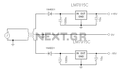
Dual Regulated Power Supply
The 7815 regulates the positive supply, while the 7915 regulates the negative supply. The transformer should have a primary rating of 240/220 volts for Europe or 120 volts for North America. The center-tapped secondary coil should be rated approximately 18...
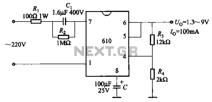
Adjustable output voltage power supply circuit MAX610
The output voltage can be calculated as follows: U = 1.3 (1 + R3 / R4) (V), where R3 and R4 are part of an adjustment potentiometer, allowing for a continuously adjustable output voltage.
The described circuit involves a voltage output...
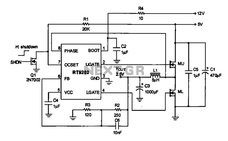
2.5V voltage regulator circuit
A 2.5V voltage regulator circuit is illustrated, which is part of a computer's motherboard. The circuit employs an oscillation circuit with the RT9202 control core chip, converting a 5V input supply into a regulated +2.5V output voltage, with the chip's...
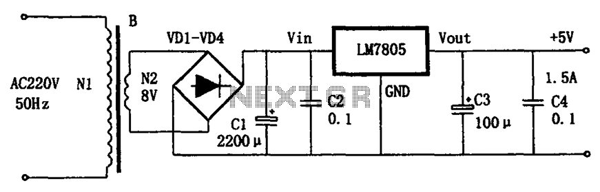
LM7805 + 5V power supply configuration
The circuit illustrated in the figure provides an output voltage of +5V and an output current of 1.5A. It comprises a power transformer, a bridge rectifier circuit consisting of diodes D1 to D4, and filter capacitor C1. Additionally, capacitors C2...
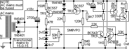
0-15 Volt 0-1A Power supply
TR1 provides a constant current to a bank of three zener diodes, thus maintaining a constant voltage independent of supply voltage variations. The resistor Rx is used to sense the PSU output current and to switch off the current to...

thrifty voltage regulator
One of the drawbacks of a three-pin voltage regulator is that the input voltage needs to be 2.5 to 3 V higher than the output voltage. This makes these integrated regulators unsuitable for battery power supplies. For instance, if the...
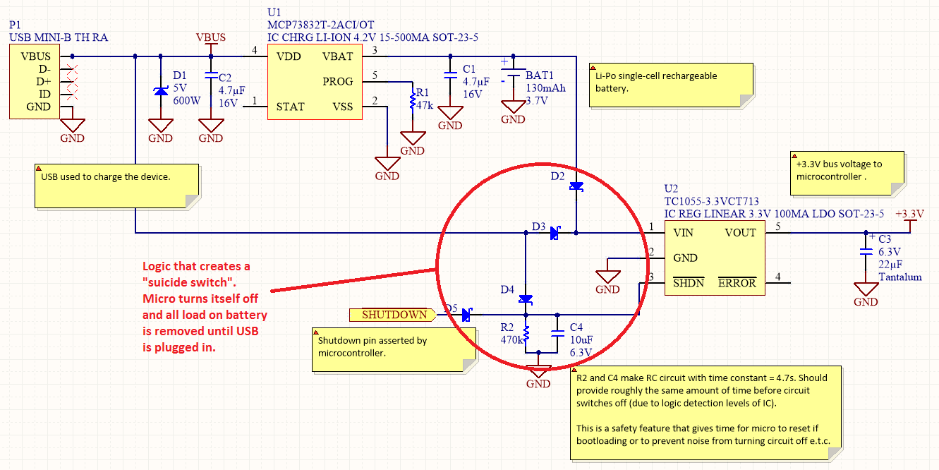
Power Management
Overview Disabling Sections of a Circuit The "Suicide Switch" Overview Power management is a significant design consideration for battery-powered devices.
Power management is a crucial aspect of circuit design, particularly in battery-powered applications where energy efficiency directly impacts the operational lifespan...
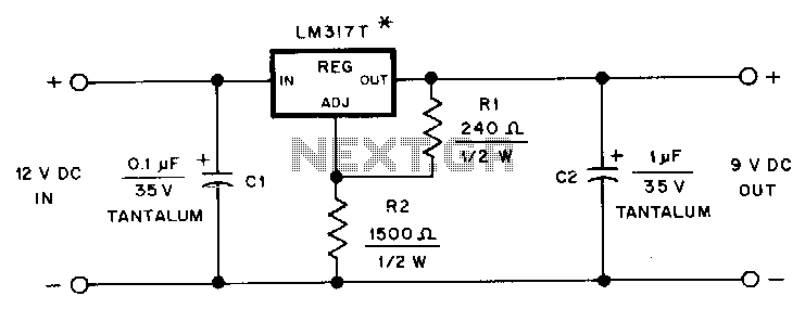
Hand-held-transceiver-dc-adapter
This adapter provides a regulated 9-V source for operating a Kenwood TR-2500 hand-held transceiver in a vehicle. The mounting tab of the LM317T is electrically connected to its output pin, which should be considered during the construction of the adapter....
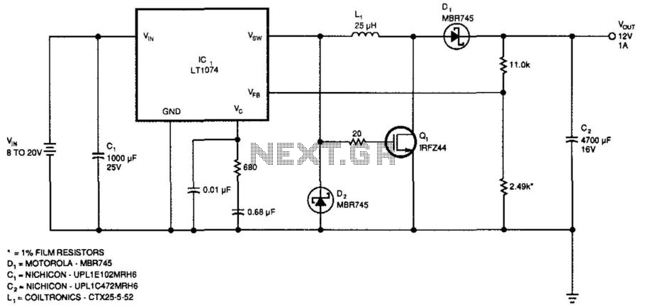
High- Or Low-Input Regulator
This regulator provides 12 V at 1 A output with an input voltage range of 8 to 20 V. The output voltage can be adjusted by changing the values of the resistors ll-kii and 2.49 kΩ to achieve 2.21 V...