


Is my zener diode labeled wrong or am i seeing a strange failure mode
#zener diode
#voltage regulator
#L7805CV
#rectifier
#electrolytic capacitor
#bridge rectifier
#power supply design
#voltage reduction
#AC to DC
#high voltage input
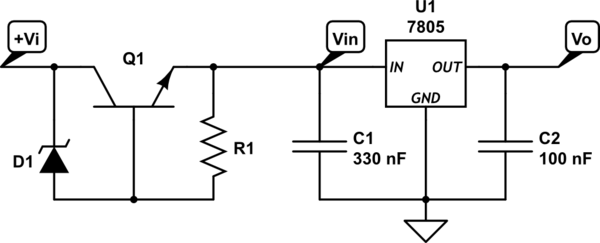
Description: A power supply circuit is designed to convert 24VAC to 5VDC. An L7805CV voltage regulator is used; however, after rectification with a bridge rectifier and smoothing with a 33µF electrolytic capacitor, the input voltage remains at 40V peak, which exceeds the maximum input voltage rating of the regulator. The regulator's datasheet suggests a "High Input Voltage Circuit," indicating that \( V_{in} = V_i - (V_Z + V_{BE}) \), but it does not provide specific guidance on the components Q1 or R1. When oriented as instructed, with the striped cathode end towards \( V_i \), the voltage at \( V_{in} \) measures the full 40V minus approximately 2 diode drops, while the voltage across the zener diode is only about 0.7V. A 33k resistor is temporarily placed to ground in lieu of the 7805 to prevent damage until the voltage limiter is correctly configured. There is a possibility of mislabeling in the circuit, and initial wiring errors resulted in smoke from an unidentified component. All tested components appear to be functioning correctly, raising the question of whether an overcurrent condition could have reversed the diode.
A power supply circuit converting 24VAC to 5VDC typically involves several key components: a transformer, a rectifier, a smoothing capacitor, and a voltage regulator. In this case, the L7805CV is utilized as the voltage regulator, which is designed to provide a stable 5V output. However, the rectification process using a bridge rectifier and a smoothing capacitor has resulted in an unexpectedly high peak input voltage of 40V.
The L7805CV has a maximum input voltage specification of 35V; thus, exceeding this limit can lead to damage or failure of the regulator. The datasheet's recommendation for a "High Input Voltage Circuit" suggests a configuration where the input voltage \( V_{in} \) is calculated as \( V_i - (V_Z + V_{BE}) \). In this setup, \( V_i \) represents the rectified input voltage, \( V_Z \) is the zener voltage, and \( V_{BE} \) is the base-emitter voltage of the transistor used in the circuit (Q1).
The issue arises when the circuit is assembled according to the instructions, as the voltage at \( V_{in} \) remains excessively high, measured at nearly the full 40V minus two diode drops. The zener diode is expected to clamp the voltage, but it is only registering about 0.7V across it, indicating that it may not be functioning as intended. To protect the L7805CV during testing, a 33k resistor has been used to ground instead of connecting directly to the regulator, which serves as a temporary solution until the voltage limiting circuit is correctly configured.
Initial attempts to wire the circuit resulted in smoke emanating from an unidentified component, suggesting that there may have been a short circuit or incorrect orientation of a component, possibly the diode. Despite this, subsequent testing indicates that the remaining components are functioning properly. This raises concerns about the potential for overcurrent conditions that could have caused the diode to fail or reverse its polarity, leading to the observed issues.
In conclusion, careful analysis and troubleshooting of the circuit are required to identify the source of the excessive input voltage and to ensure that all components are correctly oriented and functioning within their specified limits. A review of the wiring and component specifications, along with potential substitutions for the zener diode and other components, may be necessary to achieve a stable and reliable output voltage of 5VDC.A power supply circuit to bring 24VAC down to 5VDC. I have an L7805CV, but rectified (a bridge) and smoothed (a 33 F electrolytic), the input is still $40V_{peak}$, which is more than the max input voltage the regulator can take. Looking at the regulator`s datasheet, it suggests the following "High Input Voltage Circuit", which notes "$V_{in} = V_i - (V_Z + V_{BE})$", but doesn`t offer any guidance on Q1 or R1: because
when i orient it as indicated, with the striped cathode end toward $V_i$, the voltage at $V_{in}$ is the full 40V minus approx. 2 diode-drops and the voltage across the zener is only about 0. 7V. (Note that at this point, i have a 33k resistor to ground in place of the 7805 so i don`t damage it until i get the limiter right.
) It is possible that it`s really just marked wrong I made some mistakes wiring it up the first time and something let out a wisp of smoke before i cut the power, but i wasn`t able to figure out which component, and everything i`ve been able to test measures okay. Could overcurrent have somehow magically reversed this diode
A power supply circuit converting 24VAC to 5VDC typically involves several key components: a transformer, a rectifier, a smoothing capacitor, and a voltage regulator. In this case, the L7805CV is utilized as the voltage regulator, which is designed to provide a stable 5V output. However, the rectification process using a bridge rectifier and a smoothing capacitor has resulted in an unexpectedly high peak input voltage of 40V.
The L7805CV has a maximum input voltage specification of 35V; thus, exceeding this limit can lead to damage or failure of the regulator. The datasheet's recommendation for a "High Input Voltage Circuit" suggests a configuration where the input voltage \( V_{in} \) is calculated as \( V_i - (V_Z + V_{BE}) \). In this setup, \( V_i \) represents the rectified input voltage, \( V_Z \) is the zener voltage, and \( V_{BE} \) is the base-emitter voltage of the transistor used in the circuit (Q1).
The issue arises when the circuit is assembled according to the instructions, as the voltage at \( V_{in} \) remains excessively high, measured at nearly the full 40V minus two diode drops. The zener diode is expected to clamp the voltage, but it is only registering about 0.7V across it, indicating that it may not be functioning as intended. To protect the L7805CV during testing, a 33k resistor has been used to ground instead of connecting directly to the regulator, which serves as a temporary solution until the voltage limiting circuit is correctly configured.
Initial attempts to wire the circuit resulted in smoke emanating from an unidentified component, suggesting that there may have been a short circuit or incorrect orientation of a component, possibly the diode. Despite this, subsequent testing indicates that the remaining components are functioning properly. This raises concerns about the potential for overcurrent conditions that could have caused the diode to fail or reverse its polarity, leading to the observed issues.
In conclusion, careful analysis and troubleshooting of the circuit are required to identify the source of the excessive input voltage and to ensure that all components are correctly oriented and functioning within their specified limits. A review of the wiring and component specifications, along with potential substitutions for the zener diode and other components, may be necessary to achieve a stable and reliable output voltage of 5VDC.A power supply circuit to bring 24VAC down to 5VDC. I have an L7805CV, but rectified (a bridge) and smoothed (a 33 F electrolytic), the input is still $40V_{peak}$, which is more than the max input voltage the regulator can take. Looking at the regulator`s datasheet, it suggests the following "High Input Voltage Circuit", which notes "$V_{in} = V_i - (V_Z + V_{BE})$", but doesn`t offer any guidance on Q1 or R1: because
when i orient it as indicated, with the striped cathode end toward $V_i$, the voltage at $V_{in}$ is the full 40V minus approx. 2 diode-drops and the voltage across the zener is only about 0. 7V. (Note that at this point, i have a 33k resistor to ground in place of the 7805 so i don`t damage it until i get the limiter right.
) It is possible that it`s really just marked wrong I made some mistakes wiring it up the first time and something let out a wisp of smoke before i cut the power, but i wasn`t able to figure out which component, and everything i`ve been able to test measures okay. Could overcurrent have somehow magically reversed this diode
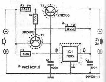
5 volts high current power supply using 7805 voltage regulator
This power supply circuit is designed to provide a high current 5-volt output using a 7805 voltage regulator along with several standard electronic components. The transistor T1 functions as a current limiter. When the voltage across resistors R2 and R3...
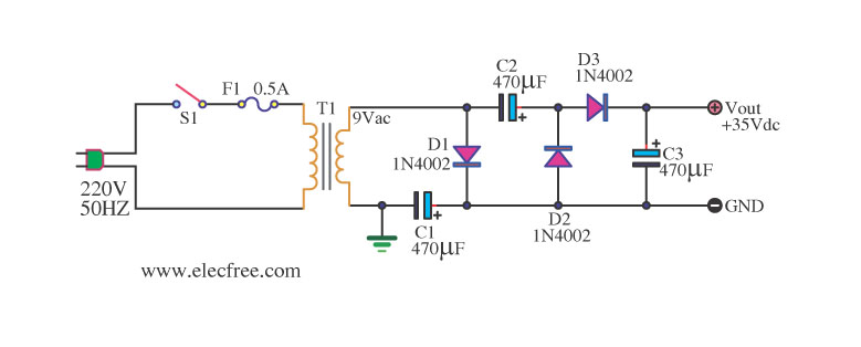
Simple AC to DC converter 9VAC to 35VDC
Simple AC to DC converter 9VAC to 35VDC. This is a basic example of an AC to DC converter model designed to be straightforward. It modifies 9VAC input to produce 35VDC output, depending on various factors.
The AC to DC converter...
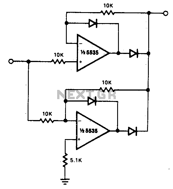
Precision full wave rectifier
The circuit facilitates precise full-wave rectification. It exhibits low output impedance for both input polarities, and the error rates remain minimal across all signal levels. It is important to note that the output will not be capable of sinking significant...
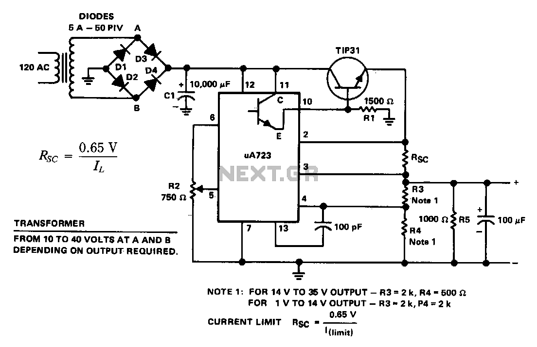
General-purpose-power-supply
The supply 6-66 can be utilized for output voltages ranging from 1 to 35 V. The line transformer must be selected to provide approximately 1.4 times the desired output voltage from the positive side of filter capacitor C1 to ground....
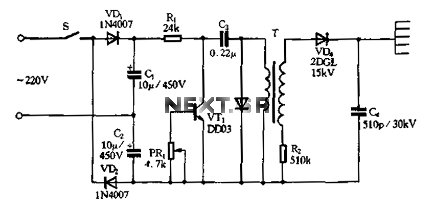
Doubling rectifier circuit in negative ion generator application circuit
Doubling rectifier circuit in a negative ion generator application circuit.
The doubling rectifier circuit is an essential component in negative ion generator applications, where it plays a crucial role in converting alternating current (AC) to direct current (DC) while also increasing...

How to build a zener diode tester
This circuit is designed to test zener diodes. It connects to a 120V AC line and amplifies the output.
The zener diode testing circuit operates by utilizing a transformer to step down the 120V AC line voltage to a more manageable...
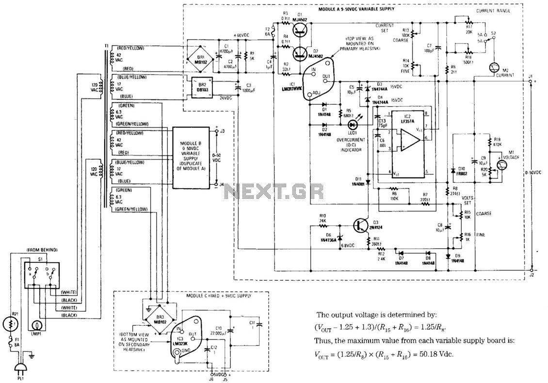
Universal Laboratory Power Supply Circuit
The design's value is derived from the use of IC1, an LM317HVK adjustable series-pass voltage regulator, which provides broad-range performance along with voltage-setting and current-limiting functions. The input to IC1 is sourced from the output of BR1, which is filtered...
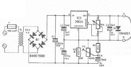
mini drill speed regulator
An integrated voltage regulator connected in reverse to a mini drill allows for speed adjustment within specific limits, maintaining a constant speed regardless of load. The electronic speed control is achieved through a voltage regulator, which can power motors requiring...
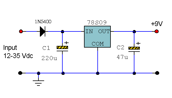
9 Volt 2 Amp Power Supply
This circuit primarily relies on the regulator for its functionality. The 78S09 regulator can provide a continuous output of up to 2 amps while ensuring a low noise and well-regulated supply. Although the circuit can operate without additional components, a...