


LCD monitor Switched Mode Power Supply
#SMPS
#LCD monitor
#LM2576-ADJ
#voltage regulator
#switched mode
#power supply
#20V
#2.3A
#adjustable voltage
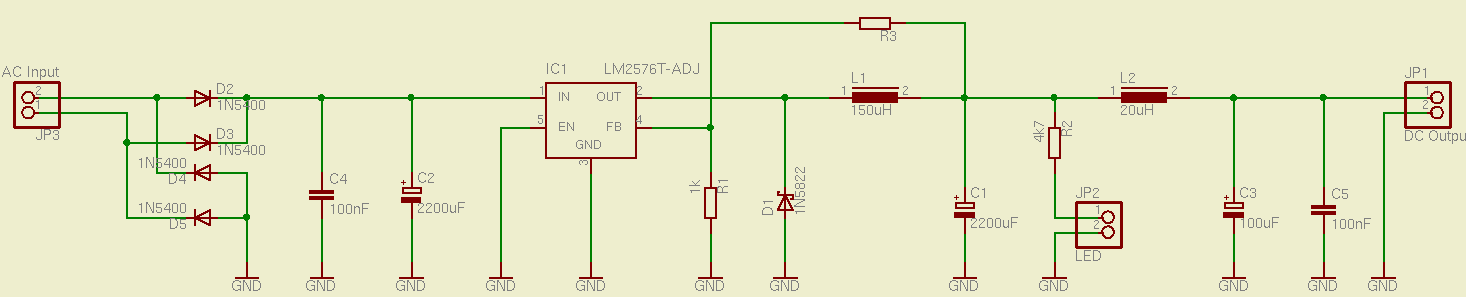
Description: This is a simple and effective switched mode power supply (SMPS) designed to power an LCD monitor. It requires 20V at 2.3A, but the power supply unit (PSU) output voltage can be adjusted in the range of 1.2V to 25V using a variable resistor (R3). The circuit employs an LM2576-ADJ regulator, which necessitates very few external components, closely following the application example provided in the National Semiconductor datasheet. This datasheet includes essential calculations for determining the component values, particularly the coil inductance and output capacitor. The regulator can handle an output current of 3A, which exceeds the required 2.3A for the LCD. The design utilizes a buck-converter topology that ensures a stable and regulated output voltage. The switching mode approach offers significantly higher efficiency compared to a linear regulator typically found in simpler circuits. The PCB layout is a single layer with wide traces for areas with substantial current flow. The assembled power supply can be seen in the accompanying figures, showing the large yellow switching toroidal inductor, which was repurposed from a broken PC power supply, along with other salvaged components, except for the regulator, which was purchased from an online electronics distributor.
The switched mode power supply (SMPS) described utilizes the LM2576-ADJ voltage regulator, which is a versatile and efficient component for DC-DC conversion. This regulator is part of the buck converter family, allowing for step-down voltage regulation. The adjustable output voltage feature is particularly beneficial, as it provides flexibility for various applications beyond the specified 20V at 2.3A for the LCD monitor.
In the schematic, the LM2576-ADJ is configured with a feedback loop that includes the variable resistor R3, enabling output voltage adjustment. The inductor plays a critical role in energy storage and transfer during the switching cycle, contributing to the overall efficiency of the power supply. The output capacitor smooths the voltage, reducing ripple and ensuring stable operation under varying load conditions.
The choice of a toroidal inductor enhances efficiency due to its lower electromagnetic interference and better magnetic properties compared to other inductor types. The design's single-layer PCB layout simplifies manufacturing and assembly while maintaining adequate thermal and electrical performance. The wide traces are essential for minimizing voltage drop and heat generation in high current paths, ensuring reliability and longevity of the power supply system.
Overall, this SMPS design exemplifies a practical approach to power supply design, emphasizing efficiency, adaptability, and the use of salvaged components, making it a valuable solution for powering electronic devices.This is a simple and effective switched mode power supply (SMPS) that I built to power a LCD monitor that I fixed a while ago. This one requires 20V at 2. 3A, but the PSU output voltage can actually be set in the range 1. 2V - 25V, with a small variable resistor (R3 in the schematic below). It uses a LM2576-ADJ regulator which requires very few exte rnal parts and as you can see from the schematic of figure 1. I didn`t go much far from the bare application example, that you can find in the National Semiconductor datasheet. There you can also find the required calculations necessary to obtain all the part values that surround the regulator, in particular the coil inductance and output capacitor.
The regulator can sustain 3A output current which is more than enough for the required 2. 3A of the LCD. It uses the simple buck-converter topology which allows to obtain a fairly stable and regulated output voltage. The switching mode approach dictates a much better efficiency than the linear regulator normally used in simple circuits.
I designed a simple one layer PCB layout, with wide traces for the paths where the current is substantial, maybe too wide ;) (see figure 2. ) You can get both the schematic and PCB in the Eagle file format from here. In figure 3. and 4. you can see the power supply already assembled and with the load (monitor) applied. You can notice the big yellow switching toroidal inductor. I got its core from a broken PC power supply and patiently winded the dozens of turns with wire I had laying around.
The remaining parts I salvaged from the junkbox, except the regulator which I bought from an online electronics distributor.
The switched mode power supply (SMPS) described utilizes the LM2576-ADJ voltage regulator, which is a versatile and efficient component for DC-DC conversion. This regulator is part of the buck converter family, allowing for step-down voltage regulation. The adjustable output voltage feature is particularly beneficial, as it provides flexibility for various applications beyond the specified 20V at 2.3A for the LCD monitor.
In the schematic, the LM2576-ADJ is configured with a feedback loop that includes the variable resistor R3, enabling output voltage adjustment. The inductor plays a critical role in energy storage and transfer during the switching cycle, contributing to the overall efficiency of the power supply. The output capacitor smooths the voltage, reducing ripple and ensuring stable operation under varying load conditions.
The choice of a toroidal inductor enhances efficiency due to its lower electromagnetic interference and better magnetic properties compared to other inductor types. The design's single-layer PCB layout simplifies manufacturing and assembly while maintaining adequate thermal and electrical performance. The wide traces are essential for minimizing voltage drop and heat generation in high current paths, ensuring reliability and longevity of the power supply system.
Overall, this SMPS design exemplifies a practical approach to power supply design, emphasizing efficiency, adaptability, and the use of salvaged components, making it a valuable solution for powering electronic devices.This is a simple and effective switched mode power supply (SMPS) that I built to power a LCD monitor that I fixed a while ago. This one requires 20V at 2. 3A, but the PSU output voltage can actually be set in the range 1. 2V - 25V, with a small variable resistor (R3 in the schematic below). It uses a LM2576-ADJ regulator which requires very few exte rnal parts and as you can see from the schematic of figure 1. I didn`t go much far from the bare application example, that you can find in the National Semiconductor datasheet. There you can also find the required calculations necessary to obtain all the part values that surround the regulator, in particular the coil inductance and output capacitor.
The regulator can sustain 3A output current which is more than enough for the required 2. 3A of the LCD. It uses the simple buck-converter topology which allows to obtain a fairly stable and regulated output voltage. The switching mode approach dictates a much better efficiency than the linear regulator normally used in simple circuits.
I designed a simple one layer PCB layout, with wide traces for the paths where the current is substantial, maybe too wide ;) (see figure 2. ) You can get both the schematic and PCB in the Eagle file format from here. In figure 3. and 4. you can see the power supply already assembled and with the load (monitor) applied. You can notice the big yellow switching toroidal inductor. I got its core from a broken PC power supply and patiently winded the dozens of turns with wire I had laying around.
The remaining parts I salvaged from the junkbox, except the regulator which I bought from an online electronics distributor.
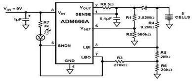
Micropower Linear Voltage Regulator in the Battery Charger Circuit
The ADM666A application note provides a detailed explanation of a low-cost battery charger circuit, including maximum output voltage, charge termination voltage calculation, battery voltage level monitoring, and circuit efficiency optimization. The ADM666A utilizes an NPN transistor and a P-channel FET....
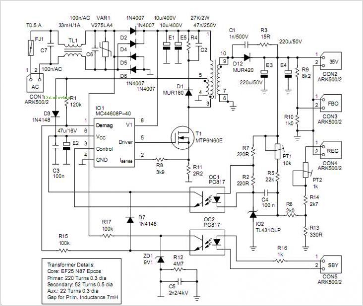
Mc44608 Smps Featuring Very Low Standby Power Consumption And Wide Range Output Voltage
MC44BS373CA: PLL Tuned UHF and VHF Audio Video High Integration Modulator MC44BS373CA The MC44BS373CA Audio and Video Modulator is designed for use in VCRs, set-top boxes, and similar devices. Manufactured by Freescale Semiconductor, Inc.
The MC44BS373CA is a highly integrated audio...
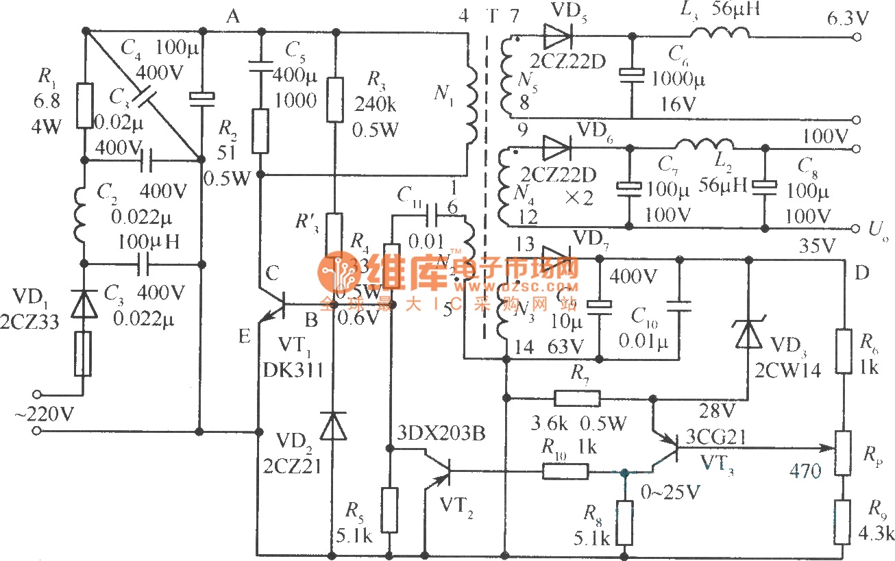
Output sampling winding isolated switching power supply
The diagram illustrates the output sampling winding of an isolated switching power supply. In the diagram, T represents a high-frequency transformer; N2 denotes the self-oscillation positive feedback winding; N3 is the error amplifier; VTS is the winding that provides the...
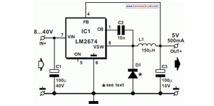
Switch Mode Power Supply
National Semiconductor has been producing and designing integrated circuits (ICs) for use in switch-mode power supplies for many years. The application of these devices is standard.
National Semiconductor has established a significant presence in the design and manufacturing of integrated circuits...
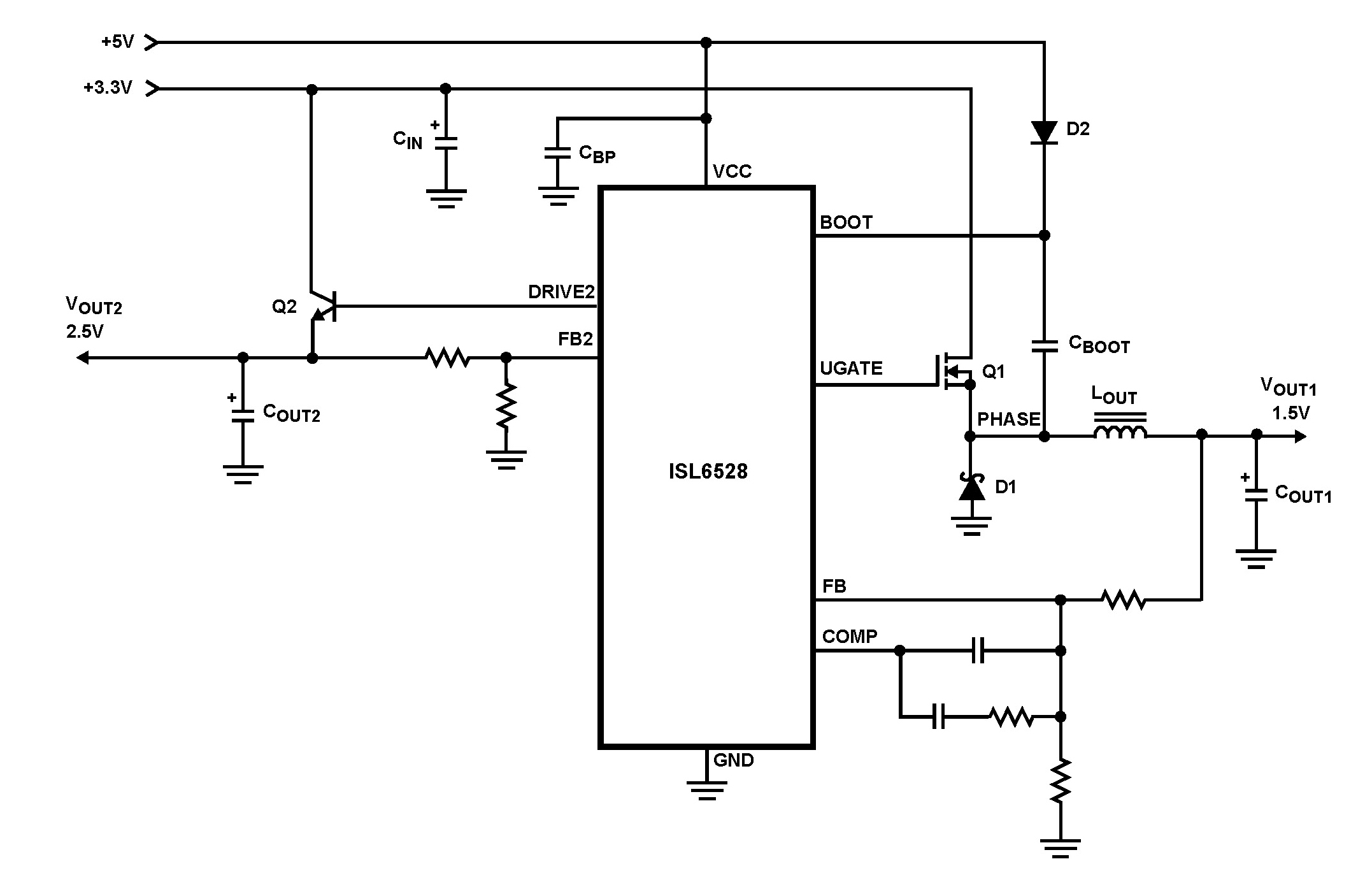
ISL6528 Dual Regulator-Standard Buck PWM and Linear Power Controller
The ISL6528 offers power control and protection for two output voltages in high-performance graphics cards and other embedded processor applications. This dual-output controller drives an N-Channel MOSFET in a standard buck topology and an NPN pass transistor in a linear...
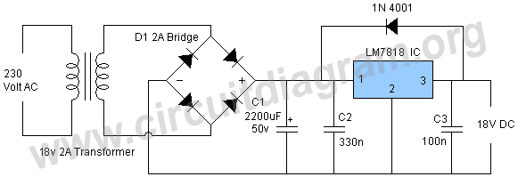
18v power supply using lm7818
This power supply operates effectively to provide a stable 18V DC output with a maximum current of 1.5A. The circuit employs an LM7818 positive voltage regulator integrated circuit (IC), which includes several built-in features such as internal current limiting, short...
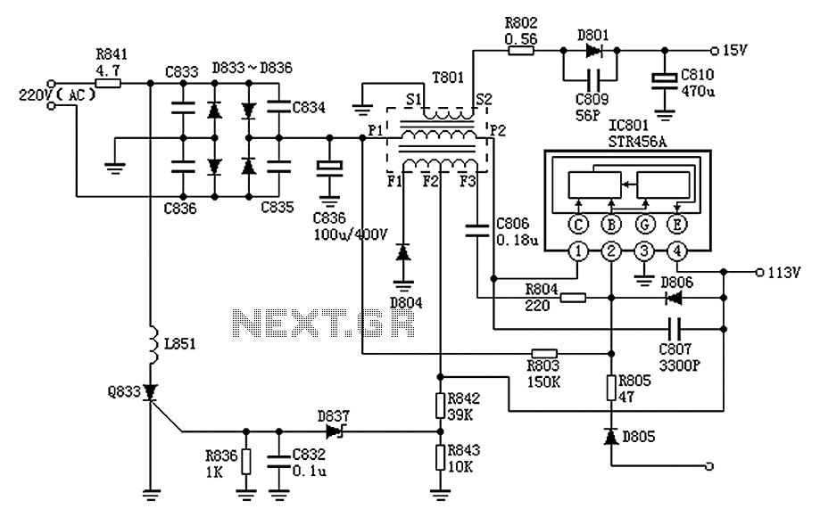
Panasonic M12H switching power supply circuit diagram
The Panasonic M12H switching power supply circuit is utilized in Panasonic models such as TC-230H, TC-2030DHN, TC-830D, and TC-840D. The circuit operates with an oscillation frequency that generates approximately 300V DC voltage at C836. The T801 transformer is involved in...
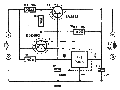
Shortcircuit protected voltage regulator
At this voltage regulator prototype the maximum current, with output shortcircuited it was only 0.5 A, so no overheating occurred. In this DC voltage regulator circuit, T1 is for current limitation. As soon as the voltage on the R2 +...
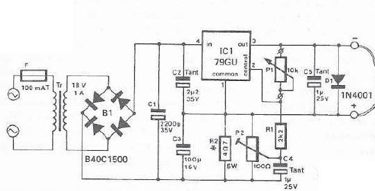
mini drill speed regulator
An integrated voltage regulator connected in reverse to a mini drill allows for speed adjustment within specific limits, maintaining a constant speed regardless of load. The electronic speed control is achieved through a voltage regulator, which can power motors requiring...