


Making A Simple Joule Thief circuit
#joule thief
#low voltage
#boost converter
#LED lighting
#energy harvesting
#DIY electronics
#battery
#circuit tutorial
#simple circuit
#power efficiency

Description: This document outlines the construction of a simple joule thief circuit. A joule thief is a versatile device, particularly useful for powering LED lights from low-voltage power supplies. It is capable of extracting energy from nearly depleted batteries, making it an environmentally friendly project. Additionally, this circuit can be utilized to create a flashlight powered by old, weak batteries.
The joule thief circuit is designed to operate efficiently with low input voltage, typically from batteries that are no longer able to power conventional devices. The fundamental components of a joule thief include a transistor, a resistor, a transformer (or inductor), and an LED.
The circuit operates by using the transistor as a switch, rapidly turning on and off to create a feedback loop that generates a higher voltage across the transformer. When the transistor is turned on, current flows through the primary winding of the transformer, building up magnetic energy. Once the transistor turns off, the magnetic field collapses, inducing a higher voltage in the secondary winding, which is then used to power the LED.
To construct a basic joule thief, the following components are typically required:
1. **Transistor**: A small-signal NPN transistor (such as 2N3904 or BC547) is commonly used.
2. **Resistor**: A resistor (around 1kΩ) is used to limit the base current to the transistor.
3. **Inductor**: A toroidal core inductor or a bifilar wound transformer with a primary and secondary winding.
4. **LED**: A light-emitting diode that will be powered by the circuit.
5. **Power Source**: A weak or nearly depleted battery, such as a single AA or AAA cell.
The assembly involves connecting the components in the following manner:
- The collector of the transistor connects to one end of the primary winding of the transformer.
- The other end of the primary winding connects to the positive terminal of the battery.
- The emitter of the transistor connects to the negative terminal of the battery.
- A resistor is placed between the base of the transistor and the positive terminal, while the secondary winding of the transformer connects to the LED.
This simple yet effective circuit exemplifies how low-voltage energy can be harnessed for practical applications, promoting sustainability and efficient energy use. The joule thief can be used in a variety of projects, including as a flashlight or in other low-power LED applications, showcasing its versatility and utility in electronics.Today I am showing you how to make a very simple joule thief. A joule thief has many applications, the best gadget that I made with was a Water Powered Lamp, soon Im going to post on a guide about it but first I need to post this guide. I used an iPhone 4S as my camera. To simplify everything, a joule thief is a circuit that helps drive an LED light even though your power supply is low. What can we do with it? We can use it to squeeze the life out of our old, almost drained, non functioning batteries. This project can also be considered as a green and environmental experiment, we can also use it as a flashlight that can be ran by an old, weak, almost drained battery.
The joule thief circuit is designed to operate efficiently with low input voltage, typically from batteries that are no longer able to power conventional devices. The fundamental components of a joule thief include a transistor, a resistor, a transformer (or inductor), and an LED.
The circuit operates by using the transistor as a switch, rapidly turning on and off to create a feedback loop that generates a higher voltage across the transformer. When the transistor is turned on, current flows through the primary winding of the transformer, building up magnetic energy. Once the transistor turns off, the magnetic field collapses, inducing a higher voltage in the secondary winding, which is then used to power the LED.
To construct a basic joule thief, the following components are typically required:
1. **Transistor**: A small-signal NPN transistor (such as 2N3904 or BC547) is commonly used.
2. **Resistor**: A resistor (around 1kΩ) is used to limit the base current to the transistor.
3. **Inductor**: A toroidal core inductor or a bifilar wound transformer with a primary and secondary winding.
4. **LED**: A light-emitting diode that will be powered by the circuit.
5. **Power Source**: A weak or nearly depleted battery, such as a single AA or AAA cell.
The assembly involves connecting the components in the following manner:
- The collector of the transistor connects to one end of the primary winding of the transformer.
- The other end of the primary winding connects to the positive terminal of the battery.
- The emitter of the transistor connects to the negative terminal of the battery.
- A resistor is placed between the base of the transistor and the positive terminal, while the secondary winding of the transformer connects to the LED.
This simple yet effective circuit exemplifies how low-voltage energy can be harnessed for practical applications, promoting sustainability and efficient energy use. The joule thief can be used in a variety of projects, including as a flashlight or in other low-power LED applications, showcasing its versatility and utility in electronics.Today I am showing you how to make a very simple joule thief. A joule thief has many applications, the best gadget that I made with was a Water Powered Lamp, soon Im going to post on a guide about it but first I need to post this guide. I used an iPhone 4S as my camera. To simplify everything, a joule thief is a circuit that helps drive an LED light even though your power supply is low. What can we do with it? We can use it to squeeze the life out of our old, almost drained, non functioning batteries. This project can also be considered as a green and environmental experiment, we can also use it as a flashlight that can be ran by an old, weak, almost drained battery.
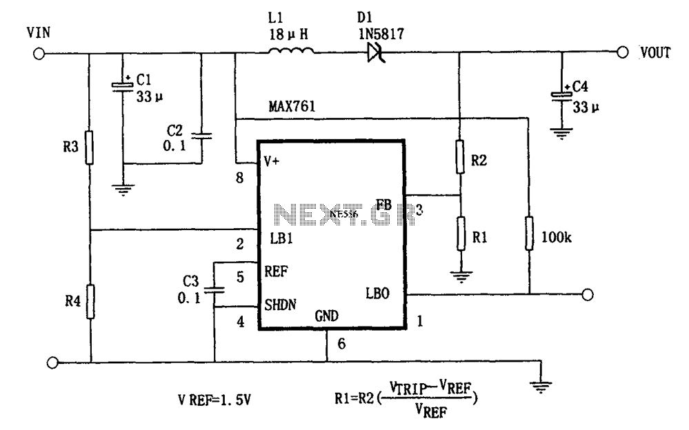
Adjustable output MAX761 boost power supply
The circuit features an efficient, low-power output voltage boost DC-DC converter, MAX761, along with a few external components that facilitate adjustable power conversion. The output voltage is determined by the ratio of resistors R1 and R2, calculated using the formula...
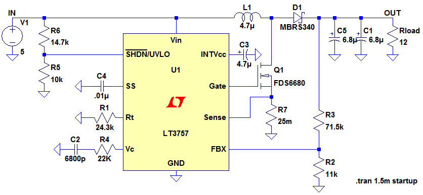
Boost Converter Design
Ignore components C1, C2, R3. The MOSFET, Q1, switches on, creating a short circuit between the right-hand side of the inductor, L1, and ground (0V). A fixed voltage of 3.3V is applied across the inductor, causing its current to ramp...
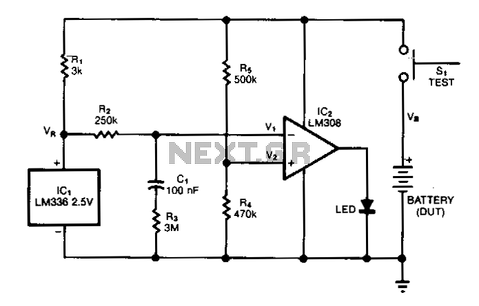
Battery-capacity-tester
The test circuit indicates the remaining capacity of a battery by measuring the duration, in seconds, that an LED remains illuminated after the test switch (S1) is activated. This circuit has demonstrated reliability in testing nickel-cadmium (NiCad), carbon, and alkaline...
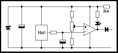
Battery Current Sensor
These controllers have an inhibit input and the effect of shorting this down to ground is to turn down the internal demand speed. So with the battery current limiter fitted, the internal demand speed can only ramp up to a...
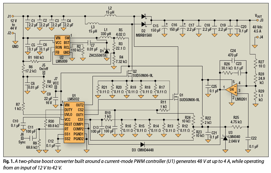
interleaving good boost converters too
The multiphase approach has long been utilized to enhance efficiency, minimize ripple, and reduce the size of capacitors and inductors in buck converters. This method can also offer similar advantages for boost converters.
The multiphase technique involves the use of multiple...
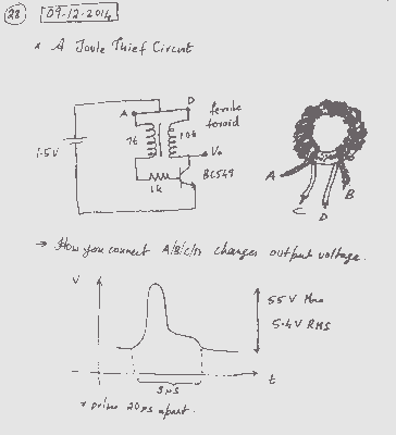
A Joule Thief Circuit
A simple voltage boost circuit known as the Joule Thief has been identified for construction.
The Joule Thief is a minimalist boost converter designed to extract energy from low-voltage sources, such as depleted batteries, and increase the voltage to a usable...
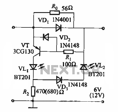
Battery state of charge indicator circuit
During the charging process, the green light-emitting diode (LED) VLi indicates that the battery is sufficiently charged, while the red light-emitting diode (LED) VLz illuminates when the battery is low.
The circuit involves two light-emitting diodes (LEDs) serving as indicators for...
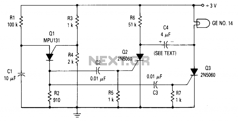
Low voltage lamp flasher
The circuit consists of a relaxation oscillator created by Q1 and an SCR flip-flop formed by Q2 and Q3. When the supply voltage is applied to the circuit, the timing capacitor C1 charges to the firing point of the Programmable...
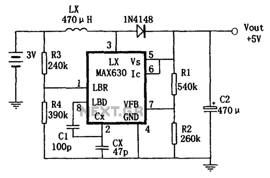
Boost has a frequency characteristic of automatic offset MAX630 power conversion
A low voltage frequency circuit utilizes the MAX630 for low battery voltage detection, functioning as an offset boost converter power supply. It is designed to maintain high efficiency (85%) while providing a DC output voltage of 5V at a current...