


Multipurpose Battery Eliminator Circuit using 4017 Decade Counter
#battery eliminator
#4017 decade counter
#voltage regulator
#rectifier
#step down transformer
#DC power supply
#AC mains
#multipurpose
#decade counter
#voltage control
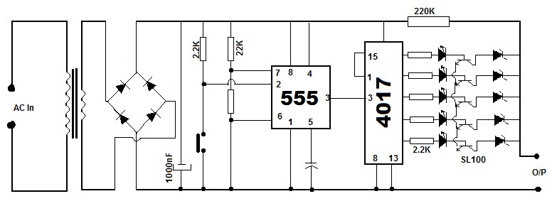
Description: Battery eliminators are circuits that create a DC power supply from AC mains. Essentially, battery eliminator circuits consist of a step-down transformer, rectifier, and voltage regulator. A simple circuit of a multipurpose battery eliminator features various output voltage ranges controlled by a decade counter IC, specifically the 4017 chip. Initially, AC is converted to DC using a rectifier circuit. A pulse generator is created using a 555 timer IC configured in monostable mode. The generated pulse is then connected to the decade counter 4017. Typically, a decade counter has ten output shift registers; however, in this circuit, only five outputs are utilized, with the sixth output employed to reset the shift register. The outputs of the shift register are connected to the bases of transistors, which are linked to voltage regulators using Zener diodes. In this setup, the NE555 timer IC functions as a monostable multivibrator, with its output pin (pin 3) connected to pin 14 of the 4017, serving as the clock input. Outputs 1, 2, 3, 4, and 5 of the 4017 are connected to pins 3, 2, 4, 7, and 10, respectively. The sixth output pin (pin 1) is connected to the reset pin (pin 15). PNP transistors, such as the SL100, are used to switch between different voltages via various Zener diodes. Each transistor is activated when it receives base voltage from the 4017, while the entire assembly of Zener diodes operates as a voltage regulator.
Battery eliminators are essential for providing a stable DC voltage from an AC source, making them useful in various applications, including powering electronic devices that typically rely on batteries. The circuit begins with a step-down transformer that reduces the high AC voltage from the mains to a lower, manageable level. This lower AC voltage is then fed into a rectifier circuit, which converts AC to pulsating DC. The pulsating DC output is further smoothed using filtering capacitors to minimize voltage ripple, ensuring a more stable DC output.
The 555 timer IC, configured in monostable mode, generates a pulse signal that acts as a clock for the decade counter 4017. This counter effectively divides the pulse frequency to control the output voltage levels. Each output from the 4017 corresponds to a specific voltage level, which is selected by activating the appropriate transistor. The PNP transistors are configured to switch on and off based on the signals received from the decade counter. When a transistor is activated, it allows current to flow through a specific Zener diode, thereby regulating the output voltage to the desired level.
Zener diodes are critical components in this circuit, as they provide voltage regulation by maintaining a constant output voltage when reverse-biased. The selection of Zener diodes determines the output voltage levels available from the battery eliminator. This design allows users to obtain multiple output voltages, making the circuit versatile for various applications.
Overall, this multipurpose battery eliminator circuit efficiently converts AC mains power into a regulated DC output, offering flexibility in voltage selection while ensuring stable performance through the use of well-established electronic components.Battery Eliminators are the circuits, which creating DC power supply from AC Mains. Basically battery eliminator circuits are the compination of step down transformer, rectifier and voltage regulator. Here is a simple circuit of a Multipurpose Battery Eliminator, which has different range of out put voltages controlled by a decade counter 4017 ic
chip. First of all we need to convert AC to DC, which is doing by a Rectifier Circuit and we are creating a pulse generator using 555 timer IC wich is wired as Monostable mode After this the pulse is connecting to the decade counter 4017. Normally decade counter have ten out put shift register but here, in this circuit we are using only 5 out puts and 6th out is using to reset this shift register.
These out puts of the shift register are connected to the base of transistors, which is connected with voltage regulators (zener diods are used in this ciruit). In this circuit NE555 timer IC is wired as monostable miltivibrator and the third pin, out put pin of timer is connected to pin number 14 of 4017, which is the clock input.
Pin 3, 2, 4, 7 and 10 of 4017 is using outputs 1, 2, 3, 4 and 5 respectively. The sixth out put pin 1 is connected to the reset pin (15). Then the SL100, the PNP transistors are using to switch between diffrent voltages by diffrent voltage Zener Diodes. Each transistors will conncted while getting base voltage from 4017 and entire zener will be connected as voltage regulator.
Battery eliminators are essential for providing a stable DC voltage from an AC source, making them useful in various applications, including powering electronic devices that typically rely on batteries. The circuit begins with a step-down transformer that reduces the high AC voltage from the mains to a lower, manageable level. This lower AC voltage is then fed into a rectifier circuit, which converts AC to pulsating DC. The pulsating DC output is further smoothed using filtering capacitors to minimize voltage ripple, ensuring a more stable DC output.
The 555 timer IC, configured in monostable mode, generates a pulse signal that acts as a clock for the decade counter 4017. This counter effectively divides the pulse frequency to control the output voltage levels. Each output from the 4017 corresponds to a specific voltage level, which is selected by activating the appropriate transistor. The PNP transistors are configured to switch on and off based on the signals received from the decade counter. When a transistor is activated, it allows current to flow through a specific Zener diode, thereby regulating the output voltage to the desired level.
Zener diodes are critical components in this circuit, as they provide voltage regulation by maintaining a constant output voltage when reverse-biased. The selection of Zener diodes determines the output voltage levels available from the battery eliminator. This design allows users to obtain multiple output voltages, making the circuit versatile for various applications.
Overall, this multipurpose battery eliminator circuit efficiently converts AC mains power into a regulated DC output, offering flexibility in voltage selection while ensuring stable performance through the use of well-established electronic components.Battery Eliminators are the circuits, which creating DC power supply from AC Mains. Basically battery eliminator circuits are the compination of step down transformer, rectifier and voltage regulator. Here is a simple circuit of a Multipurpose Battery Eliminator, which has different range of out put voltages controlled by a decade counter 4017 ic
chip. First of all we need to convert AC to DC, which is doing by a Rectifier Circuit and we are creating a pulse generator using 555 timer IC wich is wired as Monostable mode After this the pulse is connecting to the decade counter 4017. Normally decade counter have ten out put shift register but here, in this circuit we are using only 5 out puts and 6th out is using to reset this shift register.
These out puts of the shift register are connected to the base of transistors, which is connected with voltage regulators (zener diods are used in this ciruit). In this circuit NE555 timer IC is wired as monostable miltivibrator and the third pin, out put pin of timer is connected to pin number 14 of 4017, which is the clock input.
Pin 3, 2, 4, 7 and 10 of 4017 is using outputs 1, 2, 3, 4 and 5 respectively. The sixth out put pin 1 is connected to the reset pin (15). Then the SL100, the PNP transistors are using to switch between diffrent voltages by diffrent voltage Zener Diodes. Each transistors will conncted while getting base voltage from 4017 and entire zener will be connected as voltage regulator.
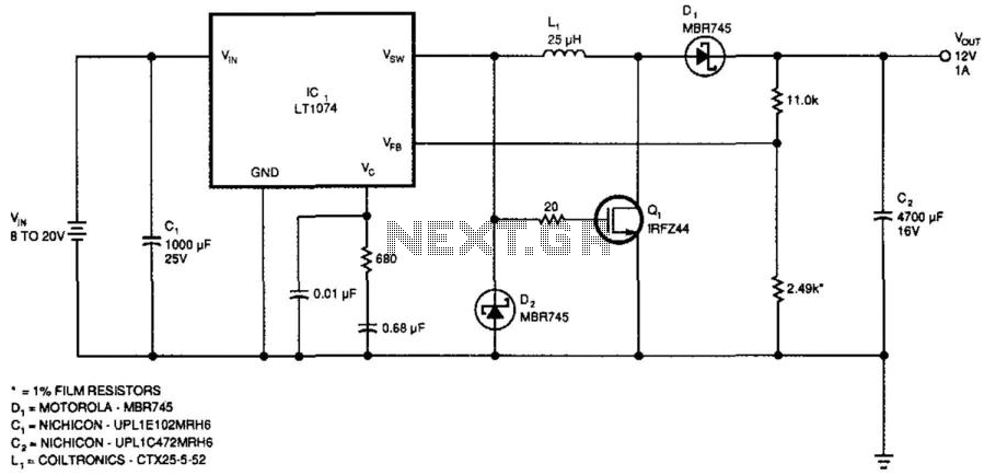
High- Or Low-Input Regulator
This regulator provides 12 V at 1 A output with an input voltage range of 8 to 20 V. The output voltage can be adjusted by changing the values of the resistors ll-kii and 2.49 kΩ to achieve 2.21 V...
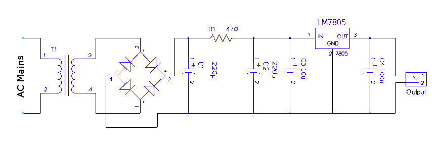
building regulated 5v dc power supply
A regulated 5-volt DC supply is essential for powering microcontroller and TTL-based circuits. The output of most wall adapters is often too rippled and impure for use in digital circuits. An inexpensive power supply can be constructed using discrete components...
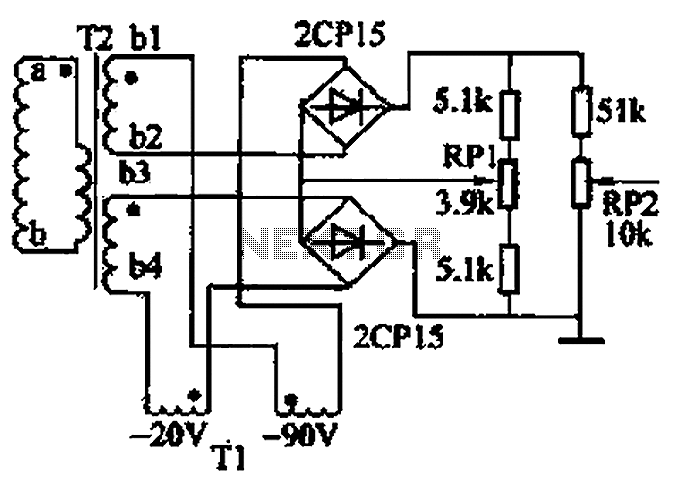
Single-phase full-wave rectifier circuit 02 phase
The closed-loop system consists of longitudinal and transverse components. The circuit operates as follows: a control circuit from the stepping motor CNC system issues a command, which the receiver detects. This signal is processed through a phase-sensitive rectifier to convert...
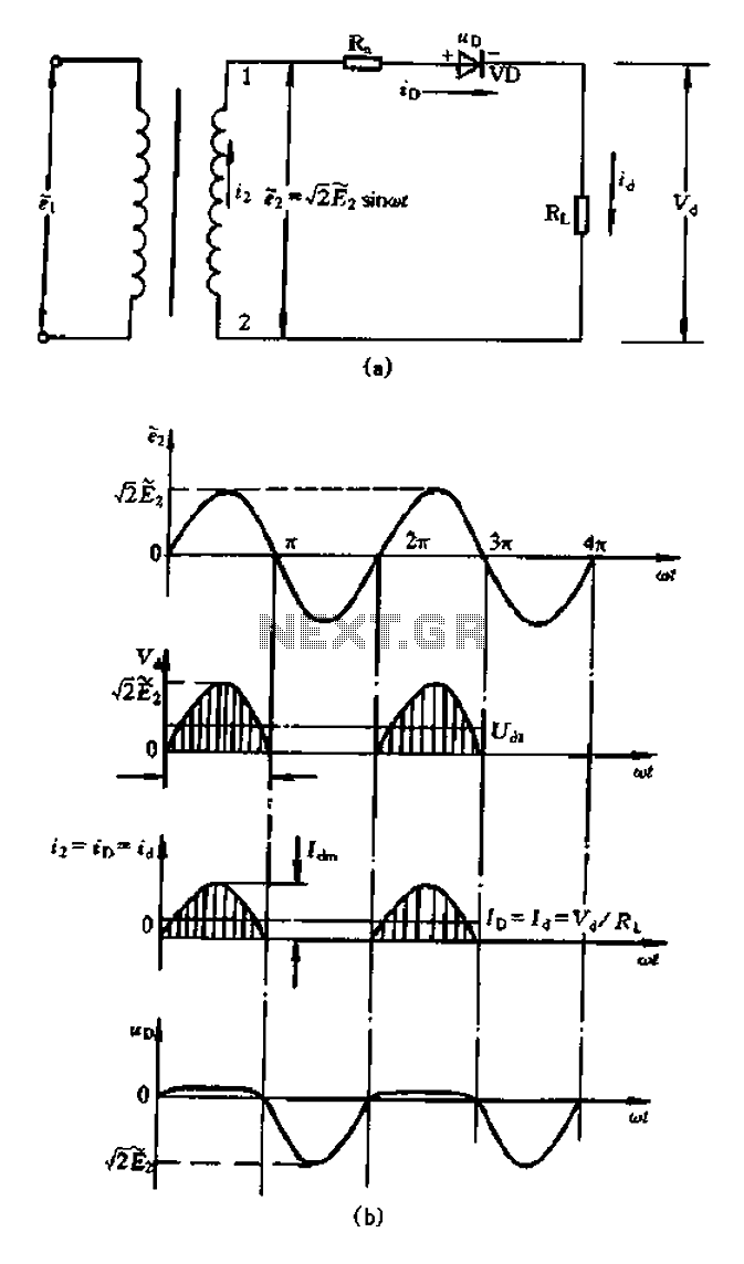
Half-wave rectifier circuit principle
A bridge rectifier capacitor filter serves as a primary power supply for current amplifier circuits. This power supply configuration is straightforward and offers enhanced performance. The bridge rectifier circuit is a full-wave rectifying circuit, meaning it converts both the positive...
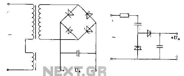
Zero rectifier regulator schematic
The pre-regulator circuit is connected to a capacitor and a resistor element. The regulator operates in its conducting direction through the input. A capacitor is connected to AC power, and in the blocking direction, it limits the current, allowing the...
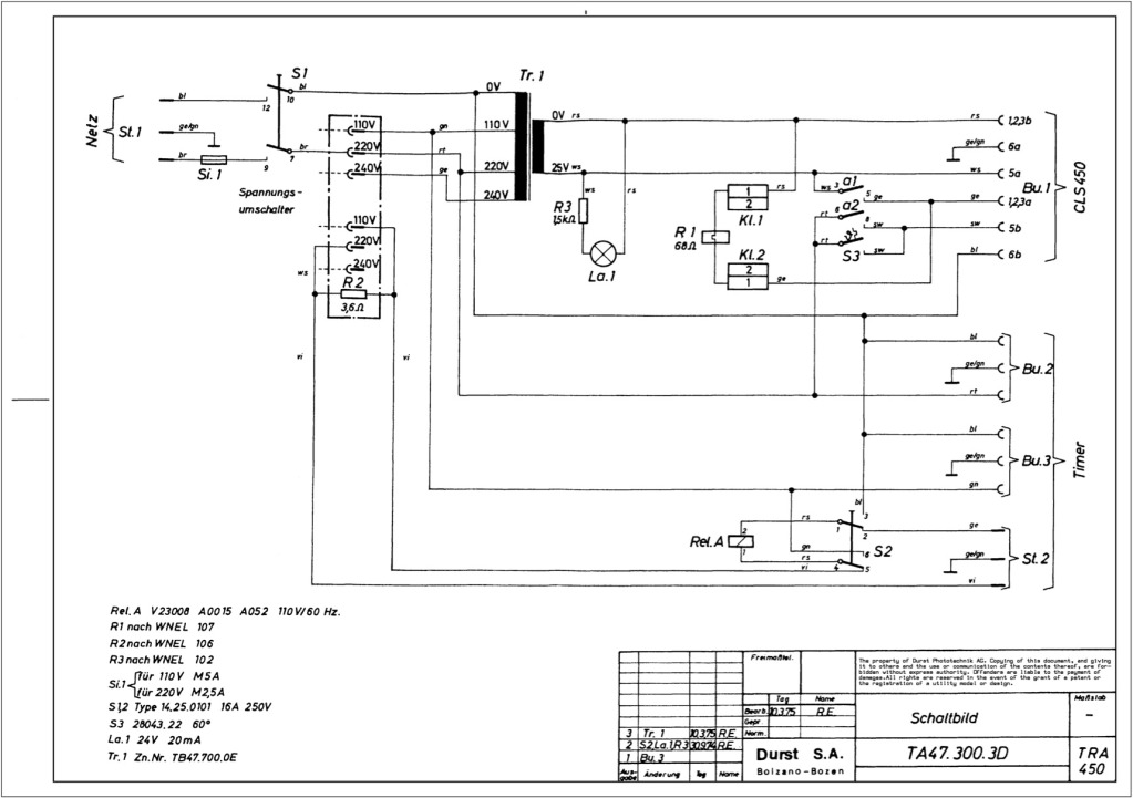
Durst power supplies EST 301 and EST 450
The regulator board of the ES301 has been inspected, revealing that the PCB contacts of the current sensing resistors R42 and R43 are severely burned. There is a nearby group of resistors that also need to be replaced, but their...

voltage regulator circuit with pass
This is a simple design for a voltage regulator circuit using a pass transistor. The design is built around the LM317T. The output current of the LM317T can be increased by incorporating an additional power transistor to share a portion...
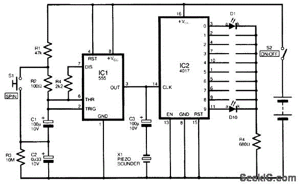
MINI ROULETTE
A circuit diagram for a mini battery-powered version of roulette is presented. This circuit utilizes a 4017 decade counter (IC2) to drive 10 LEDs. Only one LED is illuminated at any given time, which is managed by a common limiting...
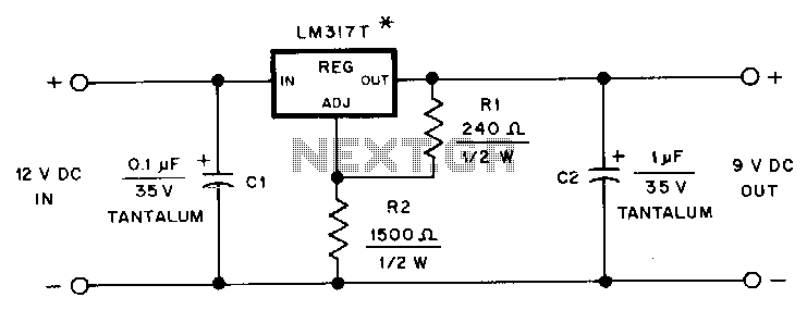
Hand-held-transceiver-dc-adapter
This adapter provides a regulated 9-V source for operating a Kenwood TR-2500 hand-held transceiver in a vehicle. The mounting tab of the LM317T is electrically connected to its output pin, which should be considered during the construction of the adapter....