


Photocell power supply (MAX630)
#photocell
#voltage regulator
#MAX630
#regulated output
#low current
#energy efficiency
#solar power
#DC power
#electronics
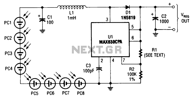
Description: This circuit provides a regulated output of either 4.8 V or 7.2 V at a current of 15 mA, utilizing a 3 V input derived from a bank of photocells. Resistor R1 should be set to 453 kΩ for a 7.2 V output and 274 kΩ for a 4.8 V output. The efficiency of the regulator is approximately 70%. This aspect should be taken into account when choosing appropriate solar cells.
The circuit operates by converting the variable voltage from the photocells into a stable output voltage. The selection of R1 is critical, as it directly influences the output voltage based on the desired level. For the 7.2 V output, a higher resistance value (453 kΩ) is required, which limits the current flow and allows the circuit to maintain the higher voltage. Conversely, a lower resistance value (274 kΩ) is utilized for the 4.8 V output, permitting more current to flow and resulting in a lower voltage.
The efficiency of around 70% indicates that the circuit converts 70% of the input power into usable output power, with the remaining 30% lost as heat or in other forms of energy dissipation. This efficiency rating is an important parameter for applications powered by solar energy, as it directly affects the selection of solar cells. The solar cells must be capable of providing sufficient current and voltage to meet the circuit's requirements while accounting for the efficiency loss.
When designing this circuit, it is essential to consider the characteristics of the photocells, including their voltage output under varying light conditions and their ability to deliver the necessary current to sustain the desired output voltage. Proper thermal management may also be necessary to prevent overheating of components, which can affect performance and reliability. Overall, careful selection of components and design considerations will ensure optimal performance of the circuit in solar-powered applications.This circuit delivers either 4.8 or 7.2 V regulated at 15 mA with a 3-V input from a bank of photocells. R1 should be 453 k? for a 7.2-V output and 274 k? for a 4.8-Vdc output. Regulator efficiency is around 70%. This should be considered when selecting suitable solar cells.
The circuit operates by converting the variable voltage from the photocells into a stable output voltage. The selection of R1 is critical, as it directly influences the output voltage based on the desired level. For the 7.2 V output, a higher resistance value (453 kΩ) is required, which limits the current flow and allows the circuit to maintain the higher voltage. Conversely, a lower resistance value (274 kΩ) is utilized for the 4.8 V output, permitting more current to flow and resulting in a lower voltage.
The efficiency of around 70% indicates that the circuit converts 70% of the input power into usable output power, with the remaining 30% lost as heat or in other forms of energy dissipation. This efficiency rating is an important parameter for applications powered by solar energy, as it directly affects the selection of solar cells. The solar cells must be capable of providing sufficient current and voltage to meet the circuit's requirements while accounting for the efficiency loss.
When designing this circuit, it is essential to consider the characteristics of the photocells, including their voltage output under varying light conditions and their ability to deliver the necessary current to sustain the desired output voltage. Proper thermal management may also be necessary to prevent overheating of components, which can affect performance and reliability. Overall, careful selection of components and design considerations will ensure optimal performance of the circuit in solar-powered applications.This circuit delivers either 4.8 or 7.2 V regulated at 15 mA with a 3-V input from a bank of photocells. R1 should be 453 k? for a 7.2-V output and 274 k? for a 4.8-Vdc output. Regulator efficiency is around 70%. This should be considered when selecting suitable solar cells.
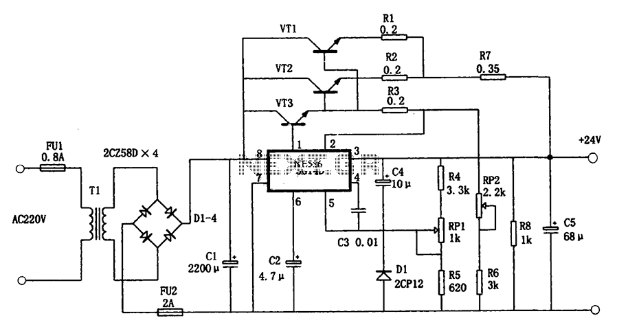
5G14D + 24V 1.9A power supply
The circuit illustrated in the figure is a +24V, 1.9A power supply design. It employs the 5G14D domestic integrated voltage regulator as the core component, supported by three external power transistors. While the 5G14D voltage regulator has a rated current...
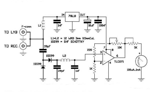
DIY Satellite Finder Circuit
A circuit has been identified that integrates a voltage regulator and filter to isolate the voltage supplied by the receiver for powering an operational amplifier (op-amp) that drives a meter. Additionally, the circuit isolates the carrier frequency from the satellite,...
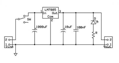
ic-7805 based 5V breadboard mini PSU circuit with explanation
A micro power supply unit (PSU) is designed to power a breadboard with a voltage output of 5 volts. It can be connected to a 9V battery, a 12V source, or any other direct current (DC) power supply ranging from...
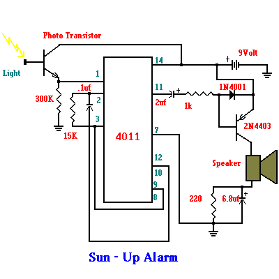
Solar power related schematics
The controller for a Hybrid Power Plant (HPP) block diagram consists of 440 Wp photovoltaic modules, a 1 kW wind turbine, and a 5 kW diesel engine as a backup. The HPP functions as a centralized PV and wind power...
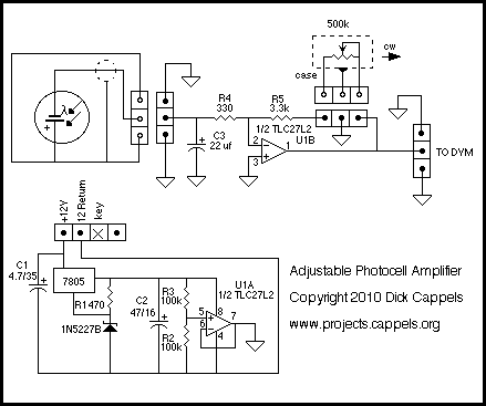
Photocell Amplifier
The output of the amplifier is to be measured on a digital voltmeter. Besides being able to accept 20 nA to 200 microamps and output voltages that range from 100 mV to 2 or 3 volts, the amplifier needed to...

12V DC Dual Power Supply Circuit with IC 7812&7912
The 78W series voltage regulators are designed to handle an input voltage of approximately 35V, while the 24V type can withstand up to 40V. It should be noted that these regulators will not operate effectively with a significant input-output voltage...

variable power supply with l200
The voltage output is controlled by a 10K variable resistor. The output voltage range is approximately 3 to 15 volts, with a current range of about 10mA minimum and 2A maximum. When the current limit is reached, the output voltage...
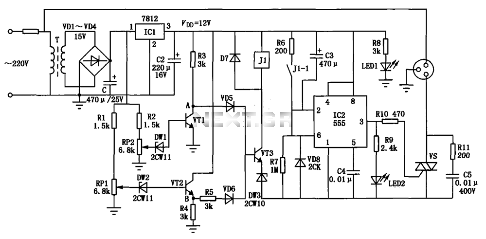
Multifunction appliance protection circuit diagram
The circuit consists of a DC voltage regulator, a delay circuit, and protection mechanisms for overvoltage and undervoltage. It utilizes the LM7812 integrated voltage regulator to provide a stable 12V output. The protection circuit samples voltage using R2 and potentiometer...
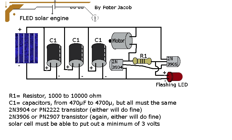
solar robot
This document outlines the construction of a trimet. The required components include three capacitors, a 2N3904 transistor, a 2N3906 transistor, a resistor with a value between 1k to 10k ohms, and a solar cell with a minimum voltage of 3...