


Regulated dual power supply circuit from single battery source
#dual power supply
#voltage regulator
#battery
#op amp
#audio pre amplifier
#instrumentation
#+9V
#-9V
#lab power supply
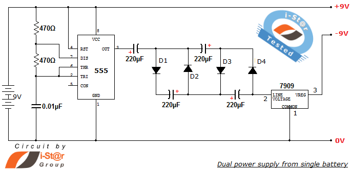
Description: How to create a dual power supply unit using a single battery for laboratory purposes. Dual voltage power supplies are particularly needed for operational amplifier experiments and some instrumentation amplifiers. Additionally, certain low-power audio preamplifiers also require dual voltage supplies. A simple dual power supply schematic is capable of producing +9V, 0V, and -9V (dual polarity and ground potential) from a single 9V battery. Custom dual power supplies can be created with various voltage ranges such as +5V, 0V, and -5V, or +12V, 0V, and -12V. This article provides the working principles and construction details of the circuit schematic utilizing a single battery source. The timer IC NE555 is configured as a free-running astable multivibrator oscillator, generating a frequency of approximately 100 kHz. The frequency of the astable multivibrator is determined by the values of the capacitors and resistors associated with the 555 timer circuit. An astable frequency calculator can assist in selecting these values. The operating voltage of the 555 timer IC ranges from approximately 3V to 16V, allowing for the implementation of the desired dual power supply with variations from 3V to 16V, in addition to the standard +9V, 0V, and -9V output.
The dual power supply circuit described utilizes a single 9V battery to generate both positive and negative output voltages along with a ground reference. This configuration is crucial for applications that require dual polarity, such as operational amplifiers and audio preamplifiers. The NE555 timer IC operates in astable mode, producing a square wave output that can be used to drive the necessary components for voltage regulation and generation.
The circuit's design typically includes a pair of capacitors and resistors connected to the NE555 timer, which dictate the frequency of oscillation. By adjusting these components, the frequency can be tailored to meet specific application requirements. The output from the NE555 is then processed through a voltage regulator or a similar circuit to achieve the desired +9V and -9V outputs.
For customization, the circuit can be modified to generate other voltage levels, such as +5V, 0V, -5V or +12V, 0V, -12V, by selecting appropriate values for the voltage regulation components. The flexibility of the NE555 timer's operating voltage allows for a wide range of applications, ensuring that the dual power supply can be adapted to various experimental setups.
Overall, this dual power supply design is a practical solution for laboratory experiments requiring stable dual voltage levels from a single power source, facilitating a broad array of electronic applications.How to create dual power supply unit using single battery for your lab prupose Dual voltage power supplies are required particularly for op amp experiments and some of the instrumentation amplifiers. Some low power audio pre amplifiers also uses dual voltage supply. Here is a simple dual power supply schematic capable of producing +9V, 0V and -9V (dual polarity and ground potential) from a single 9V battery. You can create your own dual power supplies with different ranges of +Vcc and Vcc such as +5V, 0V and -5V or +12V, 0V and -12V. This article gives the working and constructional details of the circuit schematic using single battery source.
Timer IC NE555 is configured as a free running astable multivibrator oscillator. It provides approximately 100 kHz frequency. We have already discussed about astable multivibrator. The frequency of the astable multivibrator depends on the values of capacitor and resistorsassociatedwith 555 timer circuit. Our astable frequency calculator will help you decide them. The operating voltage of 555 timer IC isapproximatelybetween 3V to 16V, so by changing the battery supply you can implement required dual power supply varies from 3V to 16V other than +9V, 0V and -9V supply.
The dual power supply circuit described utilizes a single 9V battery to generate both positive and negative output voltages along with a ground reference. This configuration is crucial for applications that require dual polarity, such as operational amplifiers and audio preamplifiers. The NE555 timer IC operates in astable mode, producing a square wave output that can be used to drive the necessary components for voltage regulation and generation.
The circuit's design typically includes a pair of capacitors and resistors connected to the NE555 timer, which dictate the frequency of oscillation. By adjusting these components, the frequency can be tailored to meet specific application requirements. The output from the NE555 is then processed through a voltage regulator or a similar circuit to achieve the desired +9V and -9V outputs.
For customization, the circuit can be modified to generate other voltage levels, such as +5V, 0V, -5V or +12V, 0V, -12V, by selecting appropriate values for the voltage regulation components. The flexibility of the NE555 timer's operating voltage allows for a wide range of applications, ensuring that the dual power supply can be adapted to various experimental setups.
Overall, this dual power supply design is a practical solution for laboratory experiments requiring stable dual voltage levels from a single power source, facilitating a broad array of electronic applications.How to create dual power supply unit using single battery for your lab prupose Dual voltage power supplies are required particularly for op amp experiments and some of the instrumentation amplifiers. Some low power audio pre amplifiers also uses dual voltage supply. Here is a simple dual power supply schematic capable of producing +9V, 0V and -9V (dual polarity and ground potential) from a single 9V battery. You can create your own dual power supplies with different ranges of +Vcc and Vcc such as +5V, 0V and -5V or +12V, 0V and -12V. This article gives the working and constructional details of the circuit schematic using single battery source.
Timer IC NE555 is configured as a free running astable multivibrator oscillator. It provides approximately 100 kHz frequency. We have already discussed about astable multivibrator. The frequency of the astable multivibrator depends on the values of capacitor and resistorsassociatedwith 555 timer circuit. Our astable frequency calculator will help you decide them. The operating voltage of 555 timer IC isapproximatelybetween 3V to 16V, so by changing the battery supply you can implement required dual power supply varies from 3V to 16V other than +9V, 0V and -9V supply.
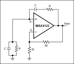
Nodal Analysis of Op Amp Circuits
This application note explains how the transfer function of most operational amplifier circuits can be derived through a straightforward process of nodal analysis.
The transfer function of operational amplifier (op amp) circuits is a critical aspect for understanding their behavior in...
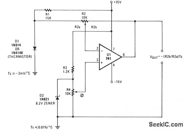
THERMOMETER ADAPTER
A simple operational amplifier and silicon diode form the core of a temperature-to-voltage converter, allowing the use of a standard voltmeter—either analog or digital—to measure temperature. User adjustments enable readings of either 10 mV or 100 mV to correspond to...
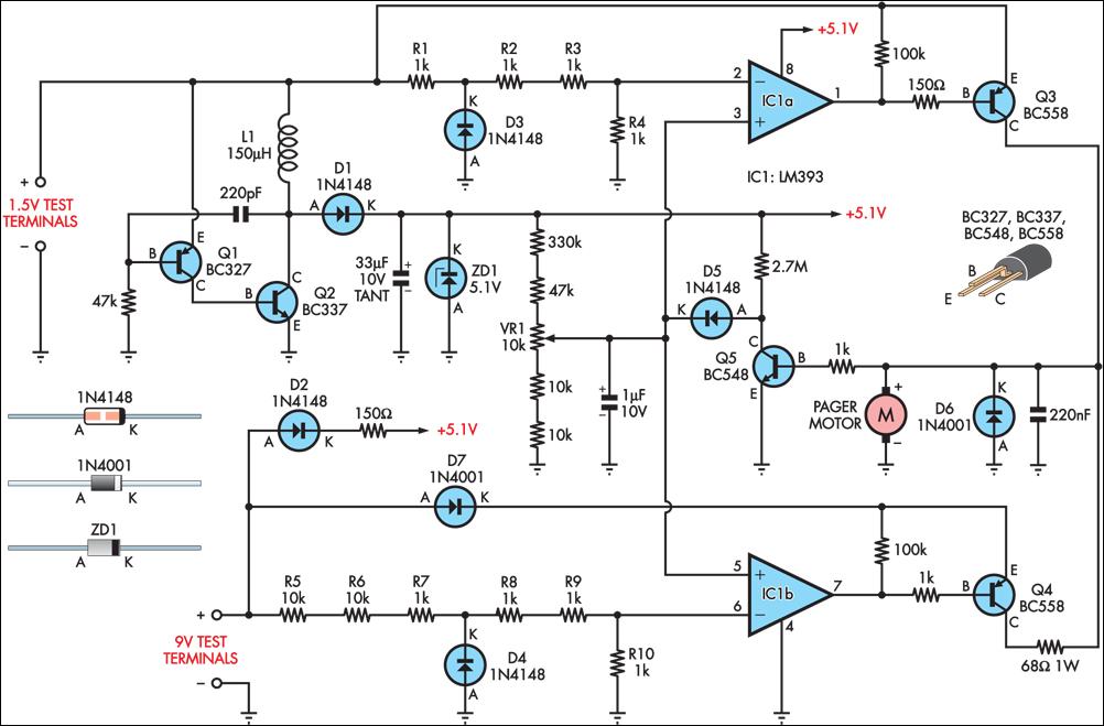
improved vibrating battery
Many blind and deaf-blind individuals utilize portable electronic devices to assist in their daily activities; however, testing the batteries used in such equipment can be challenging. While talking voltmeters are available for the blind, there is no commercially available equivalent...
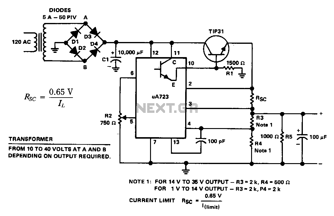
General-purpose-power-supply
The supply 6-66 can be utilized for output voltages ranging from 1 to 35 V. The line transformer must be selected to provide approximately 1.4 times the desired output voltage from the positive side of filter capacitor C1 to ground....
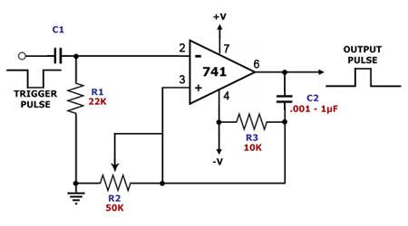
op amp monostable multivibrator
This is a monostable multivibrator circuit that utilizes a single operational amplifier. The primary component of this circuit is the 741, a general-purpose operational amplifier. A monostable multivibrator is a timing circuit that changes its output state when triggered and...
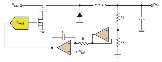
Did You Buffer The Buffered Buffer
Cypress' Dave Van Ess cautions circuit designers about the excessive and careless use of operational amplifiers, providing examples and circuit theory.
Operational amplifiers (op-amps) are widely utilized in various electronic circuits due to their versatility and performance characteristics. However, the overuse...
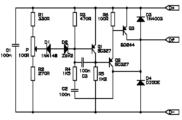
BMW R Series Motorcycle Regulator Schematic
Correctly adjusted, the voltage on the pot wiper is slightly less than half D+ (appx. 0.47*D+) and Q1 will conduct if (D+)-(Vp) > 6.2 + 0.7 + 0.7, or 0.53*(D+) > 7.6V, (D+) > 14.3V. If D+ is lower than...
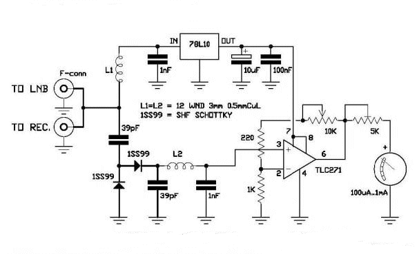
DIY Satellite Finder Circuit
A circuit has been identified that integrates a voltage regulator and filter to isolate the voltage supplied by the receiver for powering an operational amplifier (op-amp) that drives a meter. Additionally, the circuit isolates the carrier frequency from the satellite,...
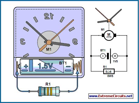
Hyper-Simple Battery Capacity Tester
The circuit described is suitable for indicating the capacity of a battery using a low-cost electric clock. By connecting a resistor across the battery terminals, the battery discharges at a faster rate than it would with the clock alone. Selecting...