


Schematics Low-Ripple Power Supply
#low-ripple
#high current
#voltage regulation
#Darlington transistor
#reference voltage
#class AB amplifier
#power supply circuit
#ZD1
#C2
#R1
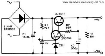
Description: This circuit can be utilized in applications requiring high current and low ripple voltage, such as in high-powered Class AB amplifiers where high-quality audio reproduction is essential. Q1 and Q2, along with resistor R2, function as a power Darlington transistor pair. Zener diode ZD1 and resistor R1 establish a reference voltage at the base of Q1. The value of ZD1 must be selected such that ZD1 = Vout - 1. Capacitor C2 can be selected based on the desired level of voltage smoothness, as its effective capacitance is amplified by the combined gains of Q1 and Q2. For instance, if a 100 µF capacitor is chosen for C2 and the minimum hFE for Q1 and Q2 is considered, the effective capacitance can be calculated as C = 100 µF × 15 (gain of Q1) × 25 (gain of Q2) = 37,000 µF.
This circuit configuration is particularly advantageous for applications where a stable output voltage is crucial, and the ability to handle high current loads with minimal voltage fluctuations is necessary. The Darlington pair configuration of Q1 and Q2 allows for significant current amplification, which is essential in driving heavy loads typically encountered in audio amplification scenarios. The choice of ZD1 is critical, as it sets the operating point for Q1, ensuring that the transistor operates within its optimal range for linearity and efficiency.
The reference voltage provided by ZD1 and R1 must be carefully calculated to ensure that Q1 remains in the active region, preventing distortion in the output signal. The selection of C2 is also vital; a larger capacitance will yield better smoothing of the output voltage, reducing ripple. The effective capacitance can be adjusted by varying C2, thereby influencing the overall performance of the amplifier. This adaptability allows for fine-tuning of the circuit to meet specific performance criteria, making it suitable for high-fidelity audio applications.
In summary, this circuit design effectively combines the advantages of a Darlington transistor configuration with careful voltage regulation and capacitance selection, resulting in a robust solution for high-current, low-ripple voltage applications such as high-powered Class AB amplifiers.This circuit can be used where a high current is required with a low-ripple voltage (such as in a high-powered class AB amplifier when high-quality reproduction is necessary). Q1, Q1 and R2 can be regarded as a power Darlington transistor. ZD1 and R1 provide a reference voltage at the base of Q1. ZD1 should be chosen thus: ZD1=Vout-1. 2. C2 can be chosen for the degree of smoothness as its value is effectively multiplied by the combined gains of Q1/Q2, if 100uF is chosen for C2, assuming minimum hfe for Q1 and Q2, C=100x15(Q1)x25(Q2)=37, 000uF.
This circuit configuration is particularly advantageous for applications where a stable output voltage is crucial, and the ability to handle high current loads with minimal voltage fluctuations is necessary. The Darlington pair configuration of Q1 and Q2 allows for significant current amplification, which is essential in driving heavy loads typically encountered in audio amplification scenarios. The choice of ZD1 is critical, as it sets the operating point for Q1, ensuring that the transistor operates within its optimal range for linearity and efficiency.
The reference voltage provided by ZD1 and R1 must be carefully calculated to ensure that Q1 remains in the active region, preventing distortion in the output signal. The selection of C2 is also vital; a larger capacitance will yield better smoothing of the output voltage, reducing ripple. The effective capacitance can be adjusted by varying C2, thereby influencing the overall performance of the amplifier. This adaptability allows for fine-tuning of the circuit to meet specific performance criteria, making it suitable for high-fidelity audio applications.
In summary, this circuit design effectively combines the advantages of a Darlington transistor configuration with careful voltage regulation and capacitance selection, resulting in a robust solution for high-current, low-ripple voltage applications such as high-powered Class AB amplifiers.This circuit can be used where a high current is required with a low-ripple voltage (such as in a high-powered class AB amplifier when high-quality reproduction is necessary). Q1, Q1 and R2 can be regarded as a power Darlington transistor. ZD1 and R1 provide a reference voltage at the base of Q1. ZD1 should be chosen thus: ZD1=Vout-1. 2. C2 can be chosen for the degree of smoothness as its value is effectively multiplied by the combined gains of Q1/Q2, if 100uF is chosen for C2, assuming minimum hfe for Q1 and Q2, C=100x15(Q1)x25(Q2)=37, 000uF.
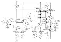
30w class ab amplifier circuit with
To configure the amplifier, set resistor R1 to its maximum value and resistor R12 to zero. After this adjustment, power on the amplifier. Adjust R1 until the measured output offset is between 30 mV and 100 mV. Once this is...
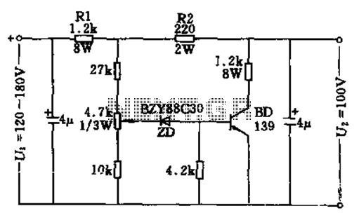
100v / 10ma regulator circuit
The circuit features no-load and short circuit protection mechanisms. To accommodate short circuit conditions, it is necessary to increase resistors R1 and R2 to allow for power dissipation; for example, R1 can be set to 1.2kΩ with a power rating...
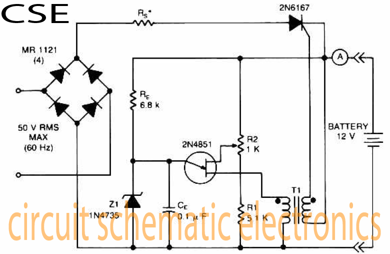
Variable charger circuit Schematic Diagram
The accumulator charger circuit must provide a voltage that matches the specifications of the batteries being charged. For a 12-volt accumulator, the output voltage should not exceed 12 volts, nor should it fall significantly below this threshold. Failure to maintain...
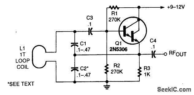
DARLINGTON TRANSISTOR OSCILLATOR
This oscillator utilizes a significant capacitance-to-inductance ratio. L1 is a one-turn coil made from a loop of #12 wire, measuring 12 inches in diameter. This circuit is advantageous for applications such as metal detectors, where a loop antenna is employed.
The...
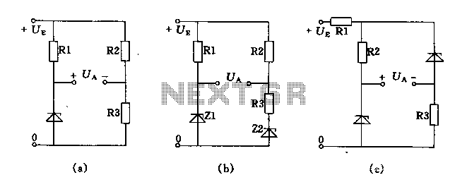
Bridge voltage regulator circuit diagram using the
The circuit depicted in Figures A, B, and C demonstrates a high voltage coefficient. When the regulator resistance \( r_z \) is held constant, the bridge configuration achieves an infinite voltage coefficient. In Figure A, the load circuit is connected...
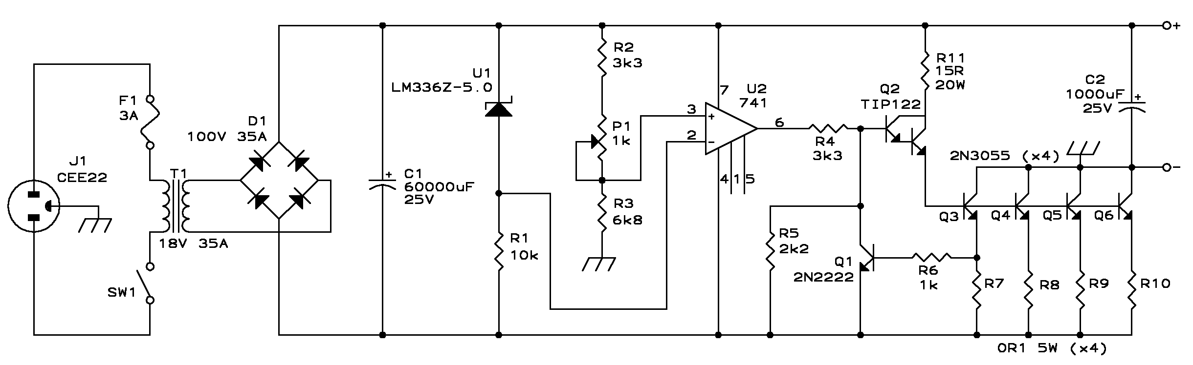
Build A 20 Amp 13.8 Volt Power Supply
Build a 20 Amp 13.8 Volt Power Supply. There are some electronic applications where it may be necessary to run relatively high current circuits, such as transformers.
To construct a 20 Amp, 13.8 Volt power supply, the following components and steps...
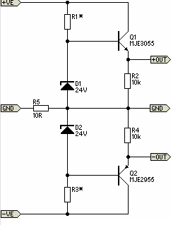
Simple Pre-Regulator
There will be many occasions when it is beneficial to utilize the P05 supply module sourced from a higher voltage supply. For instance, this could be advantageous when integrating balanced inputs.
The P05 supply module is designed to facilitate the conversion...
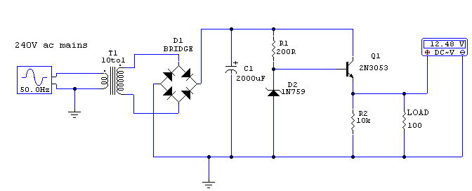
Regulated 12 Volt Supply
This circuit utilizes a 13-volt zener diode (D2) for voltage regulation. Approximately 0.7 volts are dropped across the base-emitter junction of the transistors, resulting in a higher current output of 12.3 volts. The circuit is capable of supplying loads up...
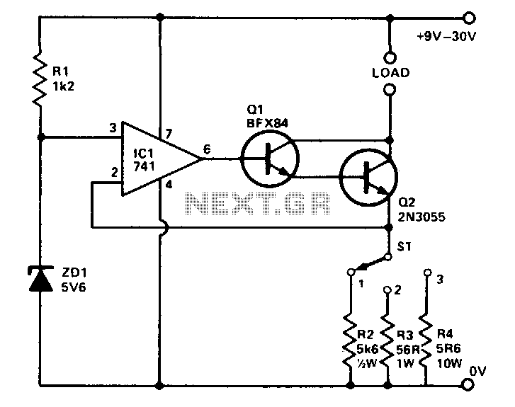
Precision buffered reference
The circuit provides three preset currents that remain constant despite variations in ambient temperature or line voltage. A temperature-stable reference voltage is produced by ZD1 and applied to the non-inverting input of IC1. A 100% feedback is applied from the...