


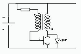
single transistor flyback Joule Thief circuit
#Joule Thief
#single transistor
#flyback
#voltage booster
#LED
#energy harvesting
#low voltage
#third coil
#flash duration
#brightness
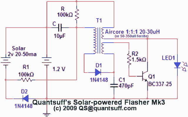
Description: This circuit is a single transistor flyback (Joule Thief) circuit that features a third coil. With it, flash duration and brightness are significantly enhanced.
The single transistor flyback circuit, commonly known as a Joule Thief, is designed to efficiently convert low voltage energy into a higher voltage output. This circuit typically utilizes a single NPN transistor, a primary coil, and a feedback mechanism that allows for the oscillation of current. The addition of a third coil in this configuration serves to increase the energy transfer efficiency and enhance the output characteristics.
In this circuit, the primary coil is connected to the base of the transistor, while the secondary coil is linked to the collector. The third coil, often referred to as the flash coil, is strategically placed to capture the energy generated during the oscillation process. When the circuit is powered, the transistor switches on and off rapidly, inducing a magnetic field in the primary coil. As the magnetic field collapses, a high voltage is generated in the secondary and third coils.
The enhanced flash duration and brightness are attributed to the third coil's ability to store and release energy more effectively. This results in a more intense output, suitable for applications such as LED flashlights or other devices requiring brief, high-intensity light bursts. The circuit's design allows for minimal component usage while maximizing performance, making it an efficient solution for low-power applications where energy conservation is critical.
Overall, this circuit exemplifies the principles of electromagnetic induction and energy conversion, showcasing how simple modifications can lead to significant improvements in performance.This circuit is a single transistor flyback (Joule Thief) circuit that features a third coil. With it, flash duration and brightness is much enhanced
The single transistor flyback circuit, commonly known as a Joule Thief, is designed to efficiently convert low voltage energy into a higher voltage output. This circuit typically utilizes a single NPN transistor, a primary coil, and a feedback mechanism that allows for the oscillation of current. The addition of a third coil in this configuration serves to increase the energy transfer efficiency and enhance the output characteristics.
In this circuit, the primary coil is connected to the base of the transistor, while the secondary coil is linked to the collector. The third coil, often referred to as the flash coil, is strategically placed to capture the energy generated during the oscillation process. When the circuit is powered, the transistor switches on and off rapidly, inducing a magnetic field in the primary coil. As the magnetic field collapses, a high voltage is generated in the secondary and third coils.
The enhanced flash duration and brightness are attributed to the third coil's ability to store and release energy more effectively. This results in a more intense output, suitable for applications such as LED flashlights or other devices requiring brief, high-intensity light bursts. The circuit's design allows for minimal component usage while maximizing performance, making it an efficient solution for low-power applications where energy conservation is critical.
Overall, this circuit exemplifies the principles of electromagnetic induction and energy conversion, showcasing how simple modifications can lead to significant improvements in performance.This circuit is a single transistor flyback (Joule Thief) circuit that features a third coil. With it, flash duration and brightness is much enhanced
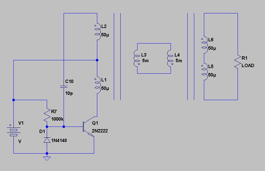
Joulethief SEC exciter and variants 64
After spending more time with the circuit, the variable potentiometer yields more beneficial results than initially anticipated. The connection between the potentiometer position and LED brightness is established, but not with the transistor's on-time. This became clear after reviewing the...

Flashing Heart
This circuit is a doorbell system featuring flashing LEDs to enhance its visual appeal. The integrated circuit IC1 (NE555) is utilized as a clock generator, configured as an astable multivibrator. The output frequency can be adjusted using the potentiometer VR1....

LED effects with ATTYNI2313
This project I made for my little daughter. It is 24 channel light illumination. The schematic is very simple 24 LEDs, 1 MCU and some additional components. The main principle is dynamic indication, which is usually implemented for control of...
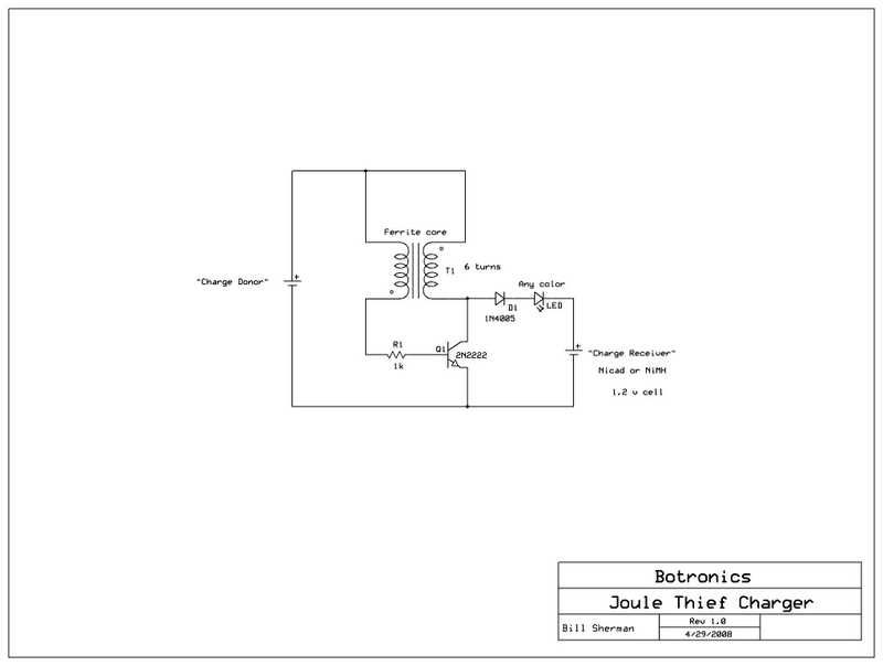
Joule Thief Charger
Allow a dead battery to energize another! An open circuit Joule Thief can generate 50 volts or more, sufficient to charge a AA or AAA NiCad or NiMH rechargeable battery.
The Joule Thief is a minimalist circuit designed to extract usable...
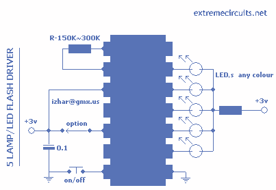
LED Flash Driver with HT2050
This circuit is based around HT2050 manufactured by HOLTEK semiconductors. It is a low cost, low-power C-MOS LSI designed for lamp and LED flash driver. It requires minimum external components. You can operate it with just two AAA cells or...
Blinking LEDs to Music
This is a straightforward project suitable for individuals with basic electronic skills. Connecting this circuit to an audio source will cause the LEDs to blink in sync with the rhythm.
The described project is an audio-activated LED circuit that visually responds...

LED Electronic roulette
The circuit utilizes a 4046 Phase-Locked Loop (PLL) that incorporates a voltage-controlled oscillator (VCO), two phase comparators, a source follower, and a Zener diode to generate a low-frequency pulsed output of approximately 40 Hz. The frequency range of the VCO...
Joule Thief Flashlight circuit
There is a requirement for a compact flashlight to illuminate small text on integrated circuits (ICs) and provide better visibility when examining disassembled components. The flashlight should have a long battery life while avoiding excessive battery consumption, such as using...
led interfacing with spartan 3 primer
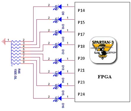
The Spartan-3 board features eight LEDs connected to FPGA I/O pins, with the cathode of each LED connected to ground through a 330-ohm resistor. To illuminate a specific LED, the corresponding FPGA control signal must be driven to a high...