


Stablised Power Supply With Short-Circuit Indication circuit
#stabilised power supply
#short-circuit indication
#voltage regulation
#audio-visual alarm
#PCB testing
#regulated output
#electronic circuits
#protection circuit
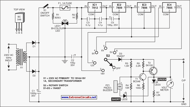
Description: This is an efficient 4-stage stabilized power supply unit designed for testing electronic circuits. It delivers well-regulated and stabilized output, which is crucial for most electronic circuits to function correctly. The circuit includes an audio-visual indicator that activates in the event of a short circuit on the PCB being tested, allowing for immediate power cut-off to protect valuable components from damage.
The 4-stage stabilized power supply unit is composed of several key components that work together to ensure reliable performance. The first stage typically consists of a transformer that steps down the AC voltage from the mains supply to a lower, manageable level. This transformer is followed by a rectifier circuit, which converts the AC voltage into pulsating DC voltage. Common rectifier configurations include bridge rectifiers using diodes, which provide full-wave rectification.
In the next stage, a smoothing capacitor is employed to reduce the ripple voltage present in the pulsating DC output. This capacitor charges during the peaks of the rectified voltage and discharges during the troughs, resulting in a more stable DC output. The value of the smoothing capacitor is chosen based on the load current requirements and the acceptable ripple voltage for the specific application.
Following the smoothing capacitor, a voltage regulation stage is implemented. This stage may utilize linear voltage regulators, such as the LM7812 for a +12V output, or adjustable regulators like the LM317, allowing for various output voltage levels. These regulators maintain a constant output voltage despite variations in input voltage or load current, ensuring that the connected electronic circuits receive a stable supply.
Finally, the last stage includes protection mechanisms such as fuses or circuit breakers to safeguard against overcurrent situations. The audio-visual indicator is implemented using a combination of LEDs and a buzzer or speaker. When a short circuit is detected, a current sensing resistor triggers the indicator, alerting the user and disconnecting power to prevent damage to the tested circuit.
Overall, this 4-stage stabilized power supply unit is an essential tool for electronic testing, providing reliable power with built-in safety features to protect both the power supply itself and the circuits under test.Here is an efficient 4-stage stabilised power supply unit for testing electronic circuits. It provides well regulated and stabilised output, which is essential for most electronic circuits to give proper results. The circuit provides an audio-visual indication if there is a short circuit in the PCB under test, so the power supply to the circuit ˜under test can be cut-off immediately to save the valuable components from damage..
The 4-stage stabilized power supply unit is composed of several key components that work together to ensure reliable performance. The first stage typically consists of a transformer that steps down the AC voltage from the mains supply to a lower, manageable level. This transformer is followed by a rectifier circuit, which converts the AC voltage into pulsating DC voltage. Common rectifier configurations include bridge rectifiers using diodes, which provide full-wave rectification.
In the next stage, a smoothing capacitor is employed to reduce the ripple voltage present in the pulsating DC output. This capacitor charges during the peaks of the rectified voltage and discharges during the troughs, resulting in a more stable DC output. The value of the smoothing capacitor is chosen based on the load current requirements and the acceptable ripple voltage for the specific application.
Following the smoothing capacitor, a voltage regulation stage is implemented. This stage may utilize linear voltage regulators, such as the LM7812 for a +12V output, or adjustable regulators like the LM317, allowing for various output voltage levels. These regulators maintain a constant output voltage despite variations in input voltage or load current, ensuring that the connected electronic circuits receive a stable supply.
Finally, the last stage includes protection mechanisms such as fuses or circuit breakers to safeguard against overcurrent situations. The audio-visual indicator is implemented using a combination of LEDs and a buzzer or speaker. When a short circuit is detected, a current sensing resistor triggers the indicator, alerting the user and disconnecting power to prevent damage to the tested circuit.
Overall, this 4-stage stabilized power supply unit is an essential tool for electronic testing, providing reliable power with built-in safety features to protect both the power supply itself and the circuits under test.Here is an efficient 4-stage stabilised power supply unit for testing electronic circuits. It provides well regulated and stabilised output, which is essential for most electronic circuits to give proper results. The circuit provides an audio-visual indication if there is a short circuit in the PCB under test, so the power supply to the circuit ˜under test can be cut-off immediately to save the valuable components from damage..

capacitor Explaining a car voltage regulator circuit
The circuit regulates approximately 12V from the car battery down to 5V for use by an Atmel AVR microcontroller. The presence of two capacitors on each side of the linear regulator LM7805 raises questions regarding their purpose. It is suggested...
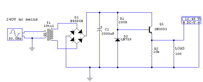
Regulated 12 Volt Supply
This circuit utilizes a 13-volt zener diode (D2) for voltage regulation. Approximately 0.7 volts are dropped across the base-emitter junction of the transistors, resulting in a higher current output of 12.3 volts. The circuit is capable of supplying loads up...
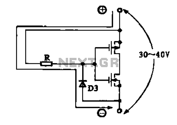
Structure and working principles of various protective circuit diagram e
Due to the varying conditions of different input signals, when an abnormal voltage is applied to the pin, protection circuits are established to create a circuit path from the LSI (large scale integration) circuits for internal protection. The structure and...
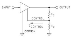
Voltage Regulator
Neither term describes a regulator, only its placement within a circuit or system. Any voltage regulator could meet the requirements, depending on its placement. A listing of Analog Voltage Regulator IC manufacturers. The types of products or devices they produce...
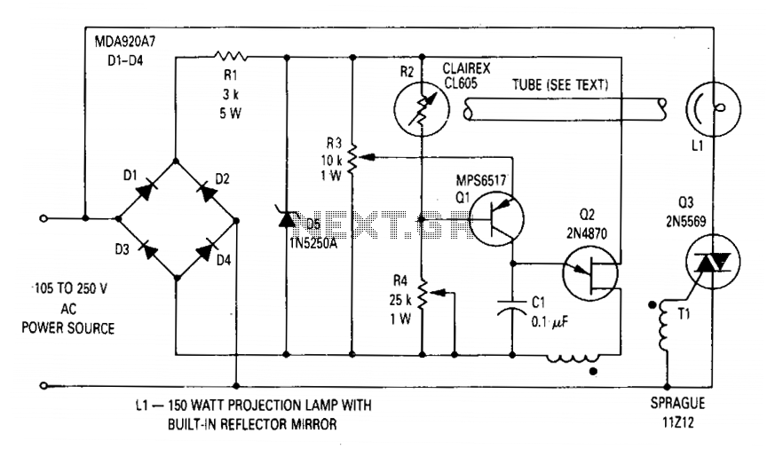
Voltage regulator for projection lamp
The circuit regulates the RMS output voltage across a load, specifically a projection lamp, to 100 volts ±2% for input voltages ranging from 105 to 250 volts AC. This regulation is achieved by indirectly sensing the light output of lamp...

Safety / Protection Circuits
To prevent deep discharge that can damage or shorten the life of a rechargeable battery, it is essential to disconnect its load before the battery is completely discharged. The circuit protects against AC line disturbances by switching off the power...
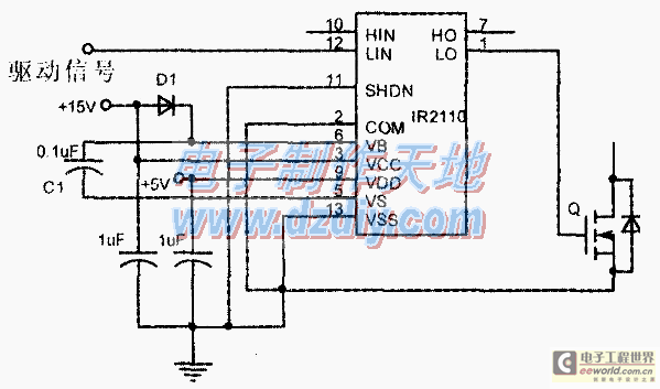
Design and making of the stabilized voltage supply of switch
Under the loading condition of the resistance, the output voltage (Uo) variable range is from 30V to 36V, with a maximum output current (Imax) of 2A. When the input voltage (U2) changes from 15V to 21V, the voltage regulation factor...

psu
The Chameleon II Power Supply Circuits convert the raw input supply into stable voltage outputs necessary for the Chameleon interfaces. The outputs provided are +5V, +12V, and -12V.
The Chameleon II Power Supply Circuits are designed to ensure reliable operation of...
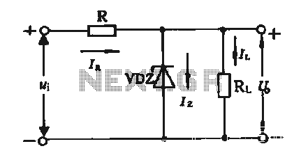
Regulator circuit silicon resistor formed
The simple voltage regulator circuit consists of a silicon regulator and a resistor. It is designed to rectify and filter DC voltage, as illustrated in the accompanying figure. The voltage regulator is connected in parallel with the load, and the...