


Suitable for pager unit cell MAX1678 high-efficiency step-up power supply configuration
#MAX1678
#step-up
#battery
#high-efficiency
#voltage boost
#pager
#single cell
#DC-DC converter
#external components
#low power
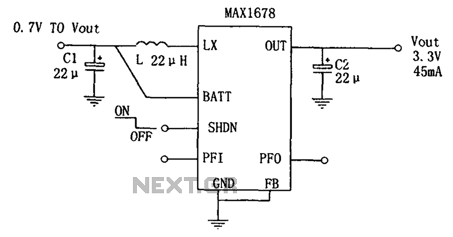
Description: As depicted in the figure, this circuit is suitable for high-efficiency single-cell battery power boosting. It comprises a MAX1678 integrated circuit and three external components. The MAX1678 is designed for low-power applications and features an ultra-small 8-pin MAX package. The circuit does not require external MOSFETs or Schottky diodes, which reduces both the cost and size of the overall system. The chip includes a battery voltage detection circuit and a noise suppression circuit. The MAX1678 employs a proprietary constant peak current control principle, allowing it to maintain low quiescent current typical of traditional PWM converters, while providing high efficiency and low output voltage ripple under full load conditions. It functions as a step-up switching power supply, capable of operating with an input voltage as low as 0.7V, and has a preset output voltage of 3.3V. Key characteristics include an efficiency exceeding 90%, a startup input voltage of 0.85V, an output current of 45mA (from 1.2V to 3.3V), a quiescent current of 37μA, and a shutdown current of 2μA. The design is compact, requiring minimal external components and featuring a straightforward structure.
The MAX1678 integrated circuit is a highly efficient boost converter designed specifically for applications powered by low-voltage batteries. Its compact 8-pin package allows for easy integration into space-constrained designs, making it ideal for portable devices. The absence of external MOSFETs and Schottky diodes not only simplifies the circuit design but also enhances reliability and reduces manufacturing costs.
The battery voltage detection circuit is a critical feature that ensures the converter operates effectively within the specified input voltage range. This feature allows the circuit to automatically adjust its operation based on the battery voltage, providing a stable output even as the battery discharges. The noise suppression circuit further enhances performance by minimizing voltage ripple, which is essential for sensitive electronic applications.
The proprietary constant peak current control mechanism employed by the MAX1678 is a significant advancement over traditional PWM control methods. This technology enables the converter to maintain high efficiency across a wide range of loads while keeping quiescent current low, which is particularly beneficial in battery-powered applications where power conservation is paramount.
With an input voltage capability starting from as low as 0.7V, the MAX1678 is particularly versatile, allowing it to be used with a variety of battery types, including single alkaline or lithium cells. The preset output voltage of 3.3V is a standard level for many digital circuits, ensuring compatibility with a wide range of devices.
In summary, the MAX1678 boost converter is an ideal solution for low-power battery applications, providing high efficiency, compact design, and ease of use, making it suitable for a variety of portable electronic devices. Its advanced features and performance characteristics make it a valuable component in the design of modern electronic systems. As shown in FIG suitable for use in high-efficiency single pager battery power boost. It is composed of a MAX1678 and three external components. MAX1678 is designed for l to tw o battery-powered low-power applications and design. It uses ultra-small 8-pin, MAX package. No external MOSFET and Schottky diode, reducing the cost and size of the system cost. Chip with a battery voltage detection circuit, the noise suppression circuit. MAX1678 uses a proprietary constant peak current control principle, it is not only to maintain the traditional PWM converters low quiescent current, full load and with high efficiency and low output voltage ripple. It consists of a step-up switching power supply, can work in 0.7V input voltage, output voltage is preset at 3.3V.
Its characteristics are: efficiency above 90%; the input voltage is 0.85V to start; 45mA output current (1.2V to rise to 3.3V); quiescent current of 37 A, shutdown current 2 A; small, small external components, simple structure.
The MAX1678 integrated circuit is a highly efficient boost converter designed specifically for applications powered by low-voltage batteries. Its compact 8-pin package allows for easy integration into space-constrained designs, making it ideal for portable devices. The absence of external MOSFETs and Schottky diodes not only simplifies the circuit design but also enhances reliability and reduces manufacturing costs.
The battery voltage detection circuit is a critical feature that ensures the converter operates effectively within the specified input voltage range. This feature allows the circuit to automatically adjust its operation based on the battery voltage, providing a stable output even as the battery discharges. The noise suppression circuit further enhances performance by minimizing voltage ripple, which is essential for sensitive electronic applications.
The proprietary constant peak current control mechanism employed by the MAX1678 is a significant advancement over traditional PWM control methods. This technology enables the converter to maintain high efficiency across a wide range of loads while keeping quiescent current low, which is particularly beneficial in battery-powered applications where power conservation is paramount.
With an input voltage capability starting from as low as 0.7V, the MAX1678 is particularly versatile, allowing it to be used with a variety of battery types, including single alkaline or lithium cells. The preset output voltage of 3.3V is a standard level for many digital circuits, ensuring compatibility with a wide range of devices.
In summary, the MAX1678 boost converter is an ideal solution for low-power battery applications, providing high efficiency, compact design, and ease of use, making it suitable for a variety of portable electronic devices. Its advanced features and performance characteristics make it a valuable component in the design of modern electronic systems. As shown in FIG suitable for use in high-efficiency single pager battery power boost. It is composed of a MAX1678 and three external components. MAX1678 is designed for l to tw o battery-powered low-power applications and design. It uses ultra-small 8-pin, MAX package. No external MOSFET and Schottky diode, reducing the cost and size of the system cost. Chip with a battery voltage detection circuit, the noise suppression circuit. MAX1678 uses a proprietary constant peak current control principle, it is not only to maintain the traditional PWM converters low quiescent current, full load and with high efficiency and low output voltage ripple. It consists of a step-up switching power supply, can work in 0.7V input voltage, output voltage is preset at 3.3V.
Its characteristics are: efficiency above 90%; the input voltage is 0.85V to start; 45mA output current (1.2V to rise to 3.3V); quiescent current of 37 A, shutdown current 2 A; small, small external components, simple structure.
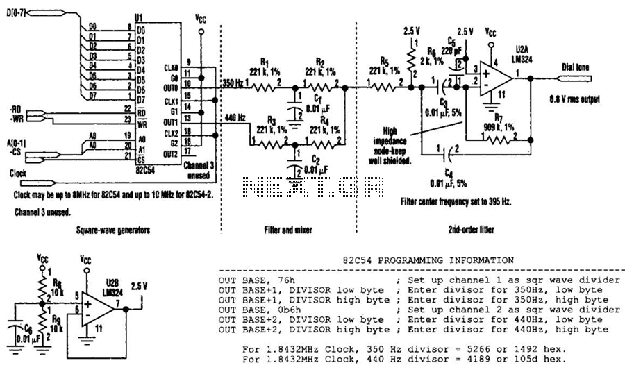
Phone Pager Circuit
This pager allows the use of in-house phone wiring as a public address (PA) system. It utilizes two tone decoders to detect a specific touch-tone key, which activates an audio amplifier.
The described system integrates existing telephone wiring to function as...
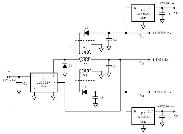
multi output dc to dc converter lm2596
This circuit diagram represents a DC to DC converter based on the LM2596. It features a single input supply with multiple voltage outputs. The input voltage range is from 15V to 40V. The circuit provides five outputs: 3.3V at 1.5A;...
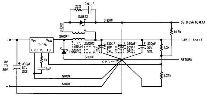
Dc-Dc Converter Circuit With 3.3V And 5V Outputs Circuit
Input voltages can range from 8 V to 30 V. The load range for the 5 V output is from 0.05 A to 5 A, while the load range for the 3.3 V output is from 0.1 A to 1...
Regulated Charge Pump
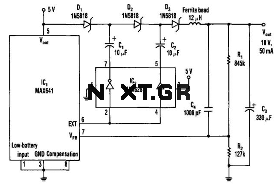
The DC-DC converter replaces a voltage tripler for the external inductor and diode typically associated with the switching regulator, IC1. Inverting and non-inverting amplifiers in the MOSFET driver (IC2) activate a diode-capacitor tripling network (D1 through D3, C1 through C3)....
Positive and negative from a battery LT1010
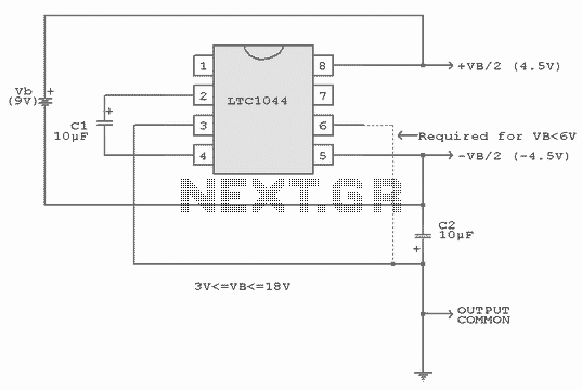
A common need in many systems is to obtain positive and negative supplies from a single battery. Where current requirements are small, the circuit shown is a simple solution. It provides symmetrical +&- output voltages, both equal to one half...
DC to DC converter electronic schematic
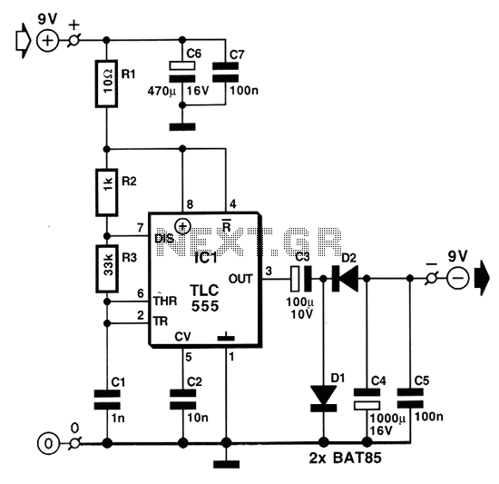
Individuals who frequently utilize battery-operated devices or require a negative voltage from a single positive source will find the following converter beneficial. This circuit can convert a 9 V positive battery voltage to a negative voltage using the well-known integrated...
improved vibrating battery
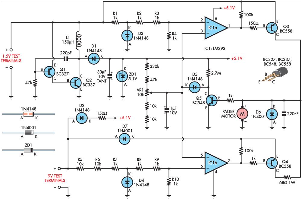
Many blind and deaf-blind individuals utilize portable electronic devices to assist in their daily activities; however, testing the batteries used in such equipment can be challenging. While talking voltmeters are available for the blind, there is no commercially available equivalent...
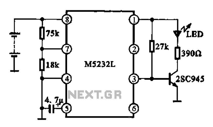
Battery voltage indication circuit
A battery voltage indication circuit that changes the status display. When the battery voltage is normal, an additional transistor drives an LED, which remains off. However, if the battery voltage falls below a critical threshold, the LED begins to flash,...
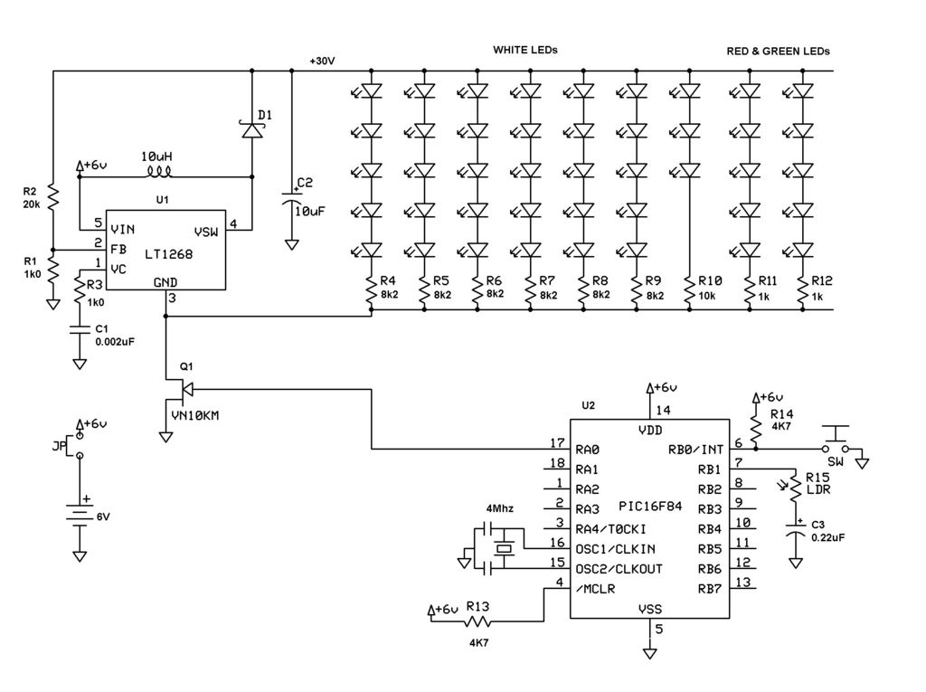
Make your own Boston Bomb
This is the circuit diagram. It is essentially a DC-DC converter, and a PIC 16F84 (or PIC 16F88) to drive it. SW1 is a test switch - push it to cause...
The described circuit involves a DC-DC converter, which is a...