


Transformerless Power Supply 30V 1A
#transformerless
#30V
#1A
#capacitor
#thyristor
#medium current
#voltage regulation
#AC to DC
#circuit schematic
#electronic design
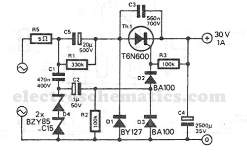
Description: This transformerless power supply circuit is designed for medium current applications. During the negative half period, the capacitor C5 is charged to the peak voltage of the network. The positive half wave will trigger the thyristor, allowing the electric charge accumulated in C5 to be transferred to C4.
This transformerless power supply circuit operates by utilizing capacitive coupling to convert AC voltage to a usable DC output without the need for a transformer. The circuit is particularly suitable for applications requiring medium current levels, typically in low-power devices.
In the operation of the circuit, during the negative half cycle of the AC input, capacitor C5 charges up to the peak voltage present in the AC line. This charging occurs due to the capacitive reactance, which allows current to flow into C5 while blocking DC components. Once C5 reaches its peak voltage, the circuit transitions to the positive half cycle.
As the AC input switches to the positive half cycle, the thyristor is triggered into conduction. This action allows the previously stored charge in C5 to flow into capacitor C4. The transfer of charge from C5 to C4 is crucial, as it provides the necessary energy to power the load connected to the output of the circuit. Capacitor C4 serves as a smoothing capacitor, helping to reduce voltage ripple and provide a more stable DC output.
The design of this transformerless power supply circuit is advantageous in applications where space and weight are critical, as it eliminates the bulkiness of a transformer. However, it is important to note that safety precautions must be taken due to the direct connection to the AC mains, which poses a risk of electric shock. Proper insulation and circuit protection measures should be implemented to ensure user safety and compliance with electrical standards.This transformerless power supply circuit is designed for medium current applications. During the negative half period, the capacitor C5 is charged to peak voltage network. Transformerless Power Supply Circuit Schematic The positive half wave will open the thyristor and the electric charge accumulated in C5 will be transferred in C4. The transport of ele..
This transformerless power supply circuit operates by utilizing capacitive coupling to convert AC voltage to a usable DC output without the need for a transformer. The circuit is particularly suitable for applications requiring medium current levels, typically in low-power devices.
In the operation of the circuit, during the negative half cycle of the AC input, capacitor C5 charges up to the peak voltage present in the AC line. This charging occurs due to the capacitive reactance, which allows current to flow into C5 while blocking DC components. Once C5 reaches its peak voltage, the circuit transitions to the positive half cycle.
As the AC input switches to the positive half cycle, the thyristor is triggered into conduction. This action allows the previously stored charge in C5 to flow into capacitor C4. The transfer of charge from C5 to C4 is crucial, as it provides the necessary energy to power the load connected to the output of the circuit. Capacitor C4 serves as a smoothing capacitor, helping to reduce voltage ripple and provide a more stable DC output.
The design of this transformerless power supply circuit is advantageous in applications where space and weight are critical, as it eliminates the bulkiness of a transformer. However, it is important to note that safety precautions must be taken due to the direct connection to the AC mains, which poses a risk of electric shock. Proper insulation and circuit protection measures should be implemented to ensure user safety and compliance with electrical standards.This transformerless power supply circuit is designed for medium current applications. During the negative half period, the capacitor C5 is charged to peak voltage network. Transformerless Power Supply Circuit Schematic The positive half wave will open the thyristor and the electric charge accumulated in C5 will be transferred in C4. The transport of ele..
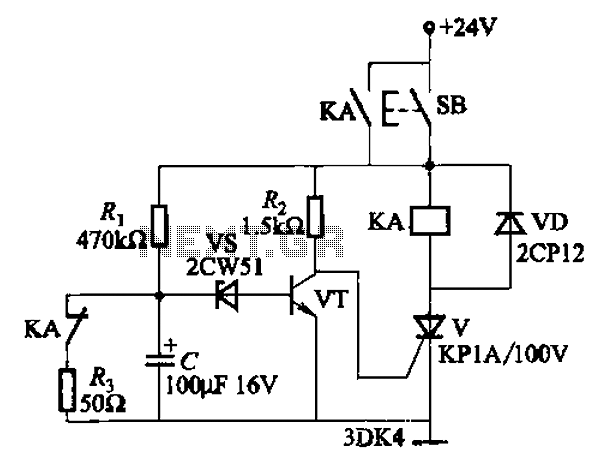
As one of the thyristor type delay circuit
This circuit is a thyristor-based delay circuit known as a cut-off delay. It allows for a specified delay period after the thyristor is activated. The delay time of the circuit can be adjusted within 10 seconds by changing the resistor...
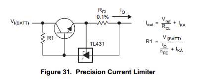
Capacitor Charging Circuit
This Korean SuperCap OEM supports usage in series configurations. Consider whether the implementation will be manual or automatic, such as with a smart battery charger or a power fail backup circuit. It is essential to balance the voltage and provide...
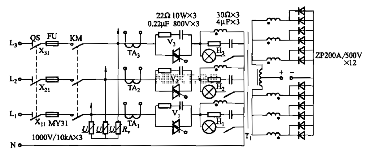
1500A-7V-phase thyristor power regulator circuit a plating
A 1500A-7V phase thyristor power regulator circuit is designed for plating applications. It consists of three major components: the main circuit, the control circuit, and the protection circuit. The control circuit includes a trigger circuit, a synchronous power supply, and...
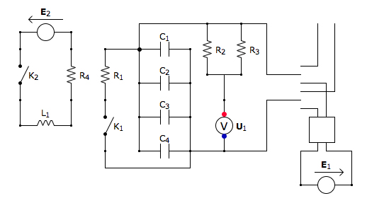
Capacitor Box Circuit
This is the discharging circuit. The red lines indicate the flow of energy from the capacitors to the terminals when the switch is in the upward position. The circuit is complete due to the connection of the terminals by Ni-Chrome...

capacitor Explaining a car voltage regulator circuit
The circuit regulates approximately 12V from the car battery down to 5V for use by an Atmel AVR microcontroller. The presence of two capacitors on each side of the linear regulator LM7805 raises questions regarding their purpose. It is suggested...
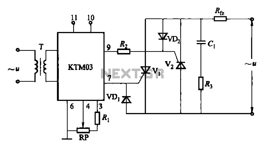
KTM03 type used to control the two anti-parallel thyristor circuit
Adjustment potentiometer RP can modify the conduction angle of thyristor Vl, vz, thus altering the voltage applied across the load Rfz.
The adjustment potentiometer (RP) serves a critical role in controlling the conduction angle of the thyristors Vl and vz within...
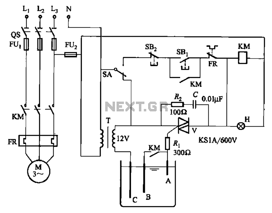
Thyristor-controlled three-level withdrawable circuits
Bidirectional thyristor control manages the trigger voltage output from the step-down transformer at 12V when the water activates the electrodes. It is part of a drawable circuit that regulates the level. The circuit includes a current-limiting resistor (Ri) to prevent...
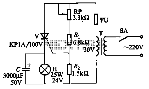
Four lights flash circuit
The circuit employs thyristor control. The flash frequency is determined by resistors Ri, RP, Rz, and capacitor C. By adjusting the electrical locator RP, the flash frequency can be varied from 0.5 Hz to several Hz.
The described circuit utilizes a...
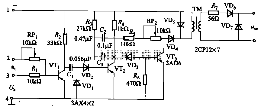
Resistive-Capacitive sinusoidal synchronous reset control transistor trigger circuit
The circuit is designed for inductive loads, specifically within a thyristor power unit, such as a three-phase step-down DC motor speed control and other applications. It is capable of delivering sufficient output power to trigger a thyristor rated at 100A....