


ttl power supply with crowbar protection
#TTL
#over-voltage protection
#crowbar circuit
#voltage stabilizer
#digital circuits
#semiconductor protection
#power regulation
#circuit safety
#electronics design
#logic circuits
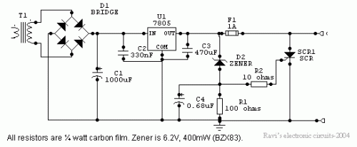
Description: Power supplies designed for use with TTL logic circuitry must protect against over-voltage, which can rapidly damage TTL chips. The duration of over-voltage that can harm TTL chips is too short to activate any conventional fuse, necessitating the use of other semiconductor circuits to provide effective protection against stabilizer failures that result in excessive voltage. This type of protection is essential for any significant TTL circuit, as stabilizer failure is a prevalent issue. Although many modern digital circuits utilize MOS devices, which are more resilient to over-voltage damage, it is uncommon to find a large digital circuit that does not include one or more TTL devices.
In the context of designing power supplies for TTL logic circuits, it is critical to incorporate protective measures against over-voltage conditions. TTL (Transistor-Transistor Logic) devices are particularly vulnerable to voltage spikes, which can occur due to various reasons, including power supply malfunctions or transient surges. The threshold for damage is often exceeded in mere microseconds, thus conventional fuses, which operate on thermal principles, are ineffective in such scenarios.
To mitigate the risk of over-voltage damage, the circuit can integrate protective components such as voltage clamping devices, which can include Zener diodes, transient voltage suppression (TVS) diodes, or metal-oxide varistors (MOVs). These components can be placed in parallel with the power supply output to shunt excess voltage away from the TTL devices, thereby safeguarding them from transient spikes.
Furthermore, the inclusion of a series resistor can help limit the current flowing into the TTL chips during an over-voltage event, providing an additional layer of protection. It is also advisable to utilize a well-regulated power supply that incorporates feedback mechanisms to maintain voltage levels within safe operating ranges, thereby reducing the likelihood of over-voltage conditions arising in the first place.
In systems where MOS devices are present, their inherent ability to tolerate higher voltage levels can be leveraged. However, the coexistence of TTL devices mandates that comprehensive over-voltage protection strategies be deployed throughout the entire circuit to ensure reliability and longevity of the components involved. Overall, the design of power supplies for TTL logic circuitry must prioritize robust protective measures to prevent catastrophic failures and maintain circuit integrity.Power supplies that are intended to be used with TTL logic circuitry must guard against over-voltage, which can destroy TTL chips very rapidly. The duration of over-voltage that can destroy TTL chips is much too brief to trigger any conventional fuse, so that only other semiconductor circuits can play any useful part in protecting a circuit against the type of failure of a stabilizer that leads to excessive voltage.
As it happens, this is the most common type of stabilizer failure, so that the protection is necessary for any TTL circuit of any significance. Many modern digital circuits make extensive use of MOS devices, which are less susceptible to damage from over-voltage, but it is unusual to find a large digital circuit, which does not contain at least one or more TTL devices..
In the context of designing power supplies for TTL logic circuits, it is critical to incorporate protective measures against over-voltage conditions. TTL (Transistor-Transistor Logic) devices are particularly vulnerable to voltage spikes, which can occur due to various reasons, including power supply malfunctions or transient surges. The threshold for damage is often exceeded in mere microseconds, thus conventional fuses, which operate on thermal principles, are ineffective in such scenarios.
To mitigate the risk of over-voltage damage, the circuit can integrate protective components such as voltage clamping devices, which can include Zener diodes, transient voltage suppression (TVS) diodes, or metal-oxide varistors (MOVs). These components can be placed in parallel with the power supply output to shunt excess voltage away from the TTL devices, thereby safeguarding them from transient spikes.
Furthermore, the inclusion of a series resistor can help limit the current flowing into the TTL chips during an over-voltage event, providing an additional layer of protection. It is also advisable to utilize a well-regulated power supply that incorporates feedback mechanisms to maintain voltage levels within safe operating ranges, thereby reducing the likelihood of over-voltage conditions arising in the first place.
In systems where MOS devices are present, their inherent ability to tolerate higher voltage levels can be leveraged. However, the coexistence of TTL devices mandates that comprehensive over-voltage protection strategies be deployed throughout the entire circuit to ensure reliability and longevity of the components involved. Overall, the design of power supplies for TTL logic circuitry must prioritize robust protective measures to prevent catastrophic failures and maintain circuit integrity.Power supplies that are intended to be used with TTL logic circuitry must guard against over-voltage, which can destroy TTL chips very rapidly. The duration of over-voltage that can destroy TTL chips is much too brief to trigger any conventional fuse, so that only other semiconductor circuits can play any useful part in protecting a circuit against the type of failure of a stabilizer that leads to excessive voltage.
As it happens, this is the most common type of stabilizer failure, so that the protection is necessary for any TTL circuit of any significance. Many modern digital circuits make extensive use of MOS devices, which are less susceptible to damage from over-voltage, but it is unusual to find a large digital circuit, which does not contain at least one or more TTL devices..
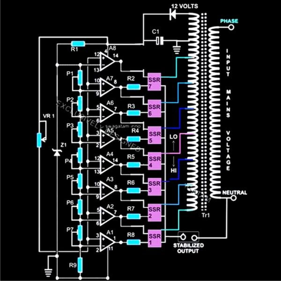
diagram shows rather simple voltage
The diagram illustrates a straightforward voltage stabilizer design capable of handling significant output power in the range of 5 to 10 KVA. The implementation of solid-state relays (SSRs) simplifies the output stage configuration and enhances accuracy, owing to modern SSRs...
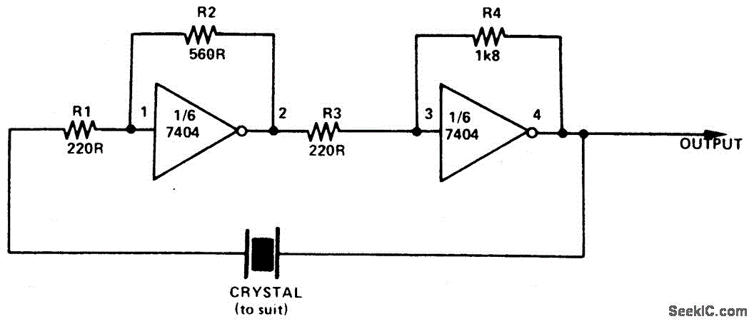
SIMPLE TTL CRYSTAL OSCILLATOR
This simple and inexpensive crystal oscillator consists of one-third of a 7404 hex inverter, four resistors, and a crystal. The inverters are biased into their linear regions by resistors R1 to R4, while the crystal provides the necessary feedback. Oscillation...
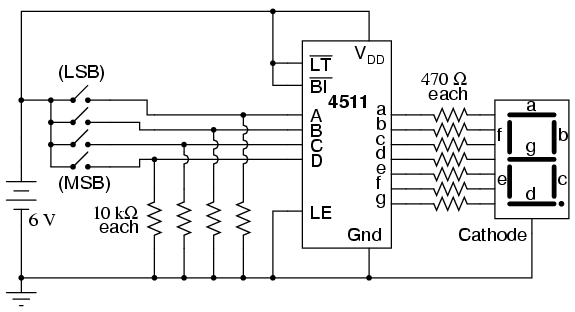
Lessons on Electric Circuits Experiments
Digital circuits are circuits that handle signals restricted to binary states of zero and a maximum value. This is in contrast to analog circuits, where signals can vary continuously within the limits set by power supply voltage and circuit resistances....
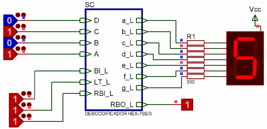
probl
The analysis of simple digital circuits involves determining the circuit's behavior, which is represented by its truth table. To achieve this, the analysis can be organized step by step. For example, consider the circuit from EX1A's Fig. 2b. Note that...
SIMPLE TTL CRYSTAL OSCILLATOR
This simple and inexpensive crystal oscillator consists of one-third of a 7404 hex inverter, four resistors, and a crystal. The inverters are biased into their linear regions by resistors R1 to R4, while the crystal provides the necessary feedback. Oscillation...
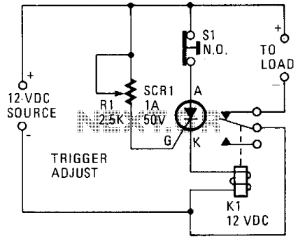
Over-voltage protection circuit
A silicon-controlled rectifier (SCR) is connected in parallel with the 12-V line and linked to a normally-closed 12-V relay, designated as K1. The gate circuit of the SCR is utilized to monitor the applied voltage. While the applied voltage remains...
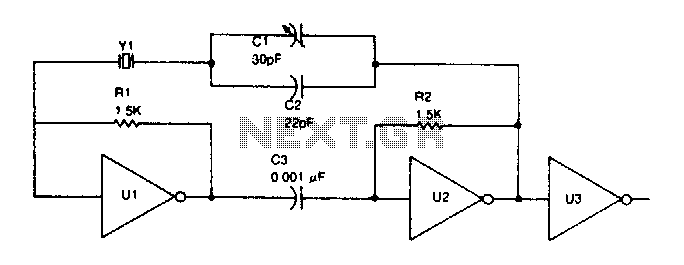
TTL oscillator
TTL inverter stages, U1 and U2, are cross-connected with a crystal Y1. A resistor in each stage biases the normally digital gates into a region where they operate as amplifiers. Inverter stage U3 is used as a buffer.
The circuit consists...

Windicator
Two TTL ICs and a handful of other components are all that is needed for a circuit that will indicate which of four buttons was pressed first, as well as lock out all other entries. A logic 0 at one...
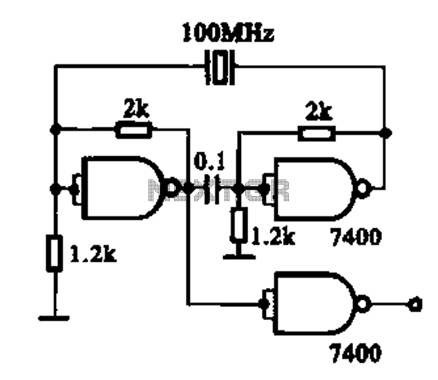
TTL integrated circuits made of a crystal oscillator
Crystal oscillator integrated circuits, specifically two diagrams of oscillator circuits with oscillation frequencies of 10 MHz and 20 MHz.
Crystal oscillators are essential components in various electronic applications, providing stable frequency references for timing and synchronization purposes. The circuits presented include...