


Variable current source 100ma-2amp
#variable current source
#op-amp
#transistor
#current control
#voltage reference
#adjustable
#100mA-2A
#fine control
#resistor
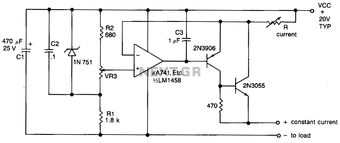
Description: The output current is determined by the resistor R located in the collector of transistor Tr2. This resistor can be adjusted to provide a range of output currents from 100 mA to 2 A. Fine control is achieved through the variable resistor VR3, which modifies the reference voltage applied to the non-inverting input of the operational amplifier. Additionally, the feedback loop from the output to the inverting input of the operational amplifier ensures that a constant voltage is maintained across resistor R, which is equal to (VCC - VIN), thereby delivering a consistent current to the load.
The described circuit utilizes a transistor-based current regulator configuration, where the output current is primarily controlled by the resistor R in the collector of transistor Tr2. The ability to vary this resistor allows for a flexible output current range, which is essential in applications requiring precise current regulation. The variable resistor VR3 plays a crucial role in fine-tuning the reference voltage supplied to the non-inverting input of the operational amplifier (op-amp).
The operational amplifier is configured in a feedback arrangement, where the output is connected back to the inverting input. This feedback mechanism is vital for maintaining the desired current output. The voltage across resistor R is kept constant, equal to (VCC - VIN), where VCC represents the supply voltage and VIN is the input voltage. This constant voltage across R ensures that the current flowing through the load remains stable, regardless of variations in load resistance or supply voltage fluctuations.
In practical applications, this circuit can be employed in power supply systems, LED drivers, or any scenario where a stable and adjustable current is necessary. The ability to set the output current between 100 mA and 2 A with fine control allows for versatility in various electronic applications, making it a valuable design in modern electronics.The output current is set by the resistor R in the collector of Tr2, which may be varied to offer a range of output currents from 100 mA to 2 A with fine control by means of VR3 which varies the reference voltage to the non-inverting input of the op amp. The feedback path from the output to the inverting input of the op amp maintains a constant voltage across R, equal to (VCC-VIN) and hence a constant current to the load given
The described circuit utilizes a transistor-based current regulator configuration, where the output current is primarily controlled by the resistor R in the collector of transistor Tr2. The ability to vary this resistor allows for a flexible output current range, which is essential in applications requiring precise current regulation. The variable resistor VR3 plays a crucial role in fine-tuning the reference voltage supplied to the non-inverting input of the operational amplifier (op-amp).
The operational amplifier is configured in a feedback arrangement, where the output is connected back to the inverting input. This feedback mechanism is vital for maintaining the desired current output. The voltage across resistor R is kept constant, equal to (VCC - VIN), where VCC represents the supply voltage and VIN is the input voltage. This constant voltage across R ensures that the current flowing through the load remains stable, regardless of variations in load resistance or supply voltage fluctuations.
In practical applications, this circuit can be employed in power supply systems, LED drivers, or any scenario where a stable and adjustable current is necessary. The ability to set the output current between 100 mA and 2 A with fine control allows for versatility in various electronic applications, making it a valuable design in modern electronics.The output current is set by the resistor R in the collector of Tr2, which may be varied to offer a range of output currents from 100 mA to 2 A with fine control by means of VR3 which varies the reference voltage to the non-inverting input of the op amp. The feedback path from the output to the inverting input of the op amp maintains a constant voltage across R, equal to (VCC-VIN) and hence a constant current to the load given
Voice amplifier transistor
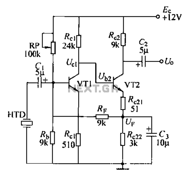
Dctl is a two-stage amplifier, with the first stage amplifying the collector voltage of transistor VT1. The second stage, represented by VT2, is proportional to the current flowing through the winding. The RF signal is applied to the sub-base of...

Transistor Mosfet pairs to drive LED cube layers
None of those devices is very suitable. The drivers aren't specified to operate with 3.3V gate signals, and although the typical graph shows that a...
The devices referenced in the original input are not appropriate for the intended application due to...
transistor ignition shematic 3
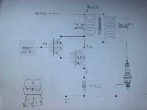
A request for assistance has been made regarding the development of a transistor ignition system to replace the point breaker in a motorcycle. The individual has researched extensively online but has not found a simple and effective circuit. The available...
Touch-on-off-electronic-switch
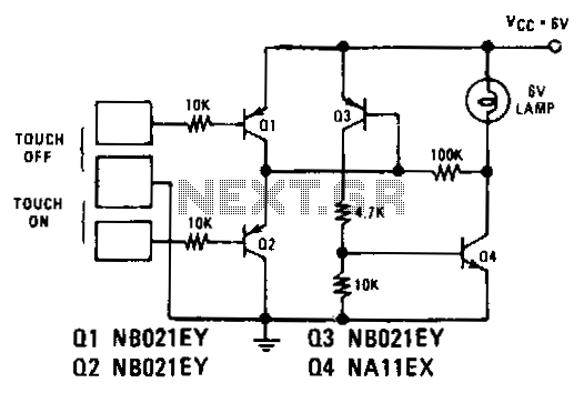
Transistors Q1 and Q2 control latches Q3 and Q4 to switch on the lamp. A high resistance from touching the electrode biases Q1 or Q2 on, setting or resetting the latch.
In this circuit, transistors Q1 and Q2 function as input...
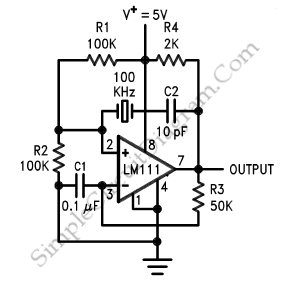
op amp Crystal Oscillator with OP AMP or Oscillator circuit built with Crystal and Op Amp
Create an oscillator circuit using an operational amplifier and a 7.68 MHz crystal. The design should be similar to the schematic provided below, but specifically tailored for a 7.68 MHz crystal. The available components include the crystal, various capacitors, resistors,...
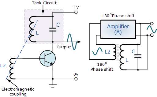
transistors LC circuit
Build the LC oscillator shown at the bottom of this page for a school project, but there are some challenges in translating the theoretical circuit into a real-world application. The understanding of the circuit's operation on paper is clear. It...
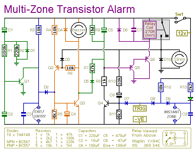
transistor based burglar alarm
This is a simple transistor-based burglar alarm circuit. Its features include automatic exit and entry delays, along with a timed bell cut-off and reset. It is designed to be used with common types of normally-closed input devices such as magnetic-reed...
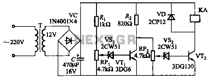
Mains undervoltage overvoltage protection circuit
The circuit employs a transistor control mechanism. When the grid voltage is within the normal range, relay KA is activated, supplying power to the load. If the grid voltage falls below the minimum allowable threshold (adjustable via potentiometer RPz) or...

Amplitude separation circuit diagram
Amplitude separation circuit. A typical amplitude separating circuit is composed of a transistor, capacitance C, and resistances RB and RC. The input signal is a composite video signal, typically with a peak-to-peak voltage of about 2V. The output signal is...