


0.1 - 3.5GHz Prescaler
#prescaler
#frequency divider
#3.5GHz
#RF measurement
#frequency meter
#signal processing
#high frequency
#GHz range
#electronic instrumentation
#RF components
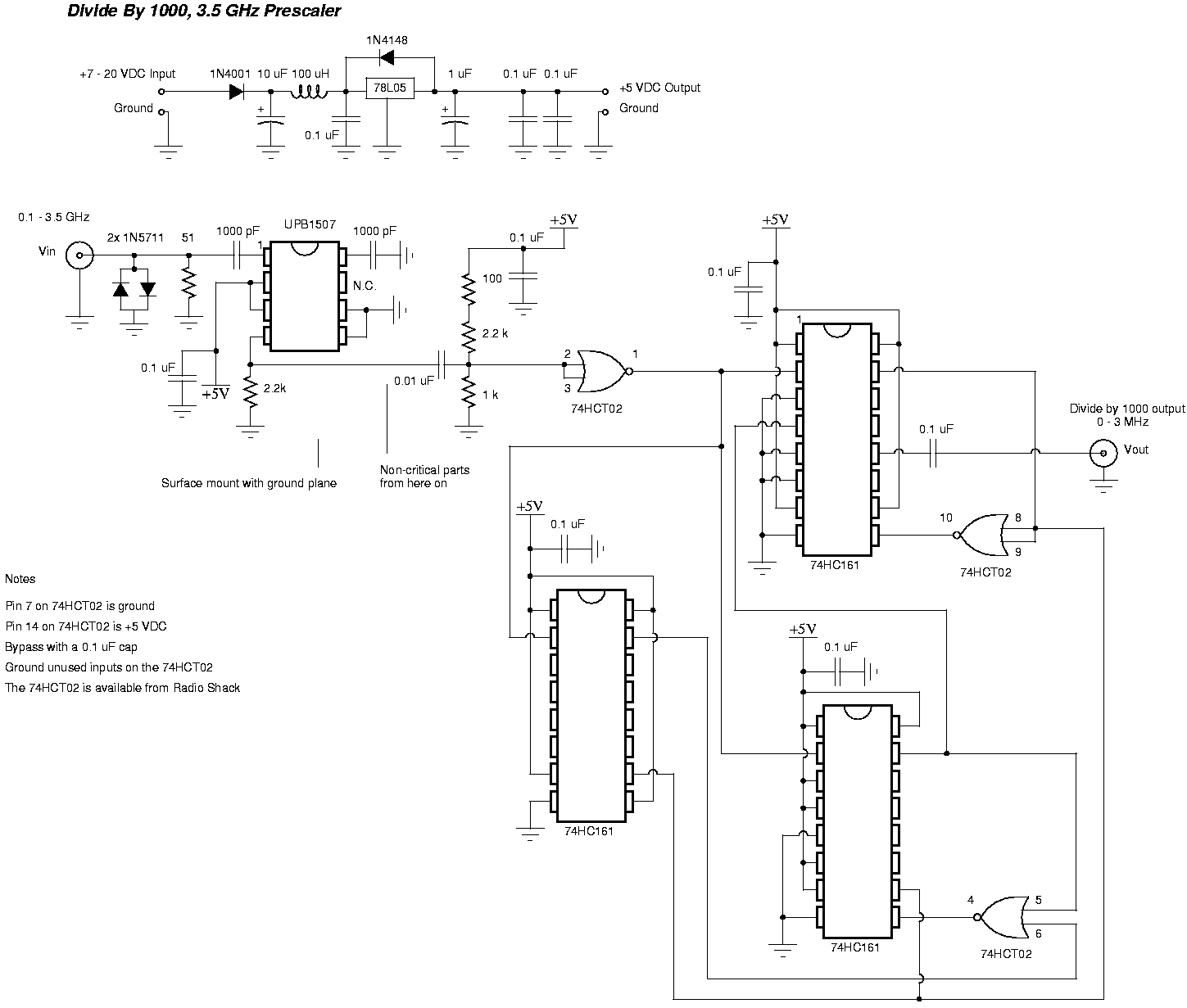
Description: This prescaler is designed to divide an input frequency by 1000. It can handle a maximum input frequency of 3.5 GHz and converts it into 3.5 MHz, which can be measured using a standard frequency meter.
The prescaler circuit consists of several key components, including a high-frequency input stage, a frequency division stage, and an output stage. The input stage is typically designed to accommodate high-frequency signals, ensuring that the circuit can effectively process signals up to 3.5 GHz. This may involve the use of RF amplifiers or impedance matching networks to optimize signal fidelity.
The frequency division is achieved through a combination of flip-flops or counters that are configured to divide the input frequency by 1000. For instance, a series of binary counters can be employed, where each stage divides the frequency by 2, ultimately achieving the desired division ratio. The choice of components in this stage is critical, as they must operate efficiently at high frequencies while maintaining low phase noise and minimal signal distortion.
The output stage is responsible for converting the divided frequency output into a format suitable for measurement. This may involve additional filtering to remove harmonics and noise, ensuring that the output signal is clean and stable. The final output frequency of 3.5 MHz can then be easily measured using standard frequency meters, making the prescaler a valuable tool in various RF applications, including communications and signal analysis.
Power supply considerations are also essential in the design of this prescaler. A stable power supply is required to ensure that the circuit operates reliably across its specified frequency range. Additionally, proper grounding and layout techniques must be employed to minimize electromagnetic interference and ensure optimal performance. Overall, the prescaler is a crucial component for frequency management in high-frequency applications.This handy prescaler divides input frequency by 1000. It takes maximum input frequency of 3. 5GHz and converts it into 3. 5MHz that may be measured using standard frequency meter.
The prescaler circuit consists of several key components, including a high-frequency input stage, a frequency division stage, and an output stage. The input stage is typically designed to accommodate high-frequency signals, ensuring that the circuit can effectively process signals up to 3.5 GHz. This may involve the use of RF amplifiers or impedance matching networks to optimize signal fidelity.
The frequency division is achieved through a combination of flip-flops or counters that are configured to divide the input frequency by 1000. For instance, a series of binary counters can be employed, where each stage divides the frequency by 2, ultimately achieving the desired division ratio. The choice of components in this stage is critical, as they must operate efficiently at high frequencies while maintaining low phase noise and minimal signal distortion.
The output stage is responsible for converting the divided frequency output into a format suitable for measurement. This may involve additional filtering to remove harmonics and noise, ensuring that the output signal is clean and stable. The final output frequency of 3.5 MHz can then be easily measured using standard frequency meters, making the prescaler a valuable tool in various RF applications, including communications and signal analysis.
Power supply considerations are also essential in the design of this prescaler. A stable power supply is required to ensure that the circuit operates reliably across its specified frequency range. Additionally, proper grounding and layout techniques must be employed to minimize electromagnetic interference and ensure optimal performance. Overall, the prescaler is a crucial component for frequency management in high-frequency applications.This handy prescaler divides input frequency by 1000. It takes maximum input frequency of 3. 5GHz and converts it into 3. 5MHz that may be measured using standard frequency meter.
Digital-frequency-meter
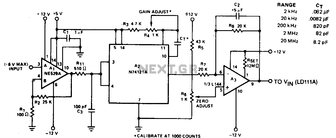
The circuit converts frequency to voltage by taking the average DC value of the pulses from the 74121 monostable multivibrator. The one-shot is triggered by the positive-going AC signal at the input of the 529 comparator. The amplifier functions as...

Decade frequency divider
In the next stage, the product of R2 and C2 should be ten times that of the preceding stage (±2%). R2 should be between 27K and 10M. Additional components include C1 and C2 with a capacitance of 0.047 µF (±1%),...
High Frequency Generator Circuit
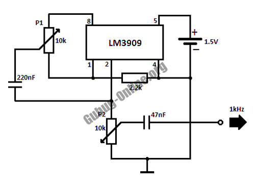
This circuit design for a high-frequency waveform generator is highly beneficial for electronic experiments and designs. The circuit generates sine wave oscillations, but it can also be modified to produce triangle or square wave functions.
The high-frequency waveform generator circuit typically...
Frequency divider
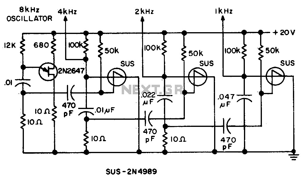
Spikes in the center of a sawtooth wave are eliminated in this circuit by triggering at specific intervals.
This circuit is designed to mitigate unwanted spikes that occur in the center of a sawtooth waveform. The sawtooth wave, characterized by its...
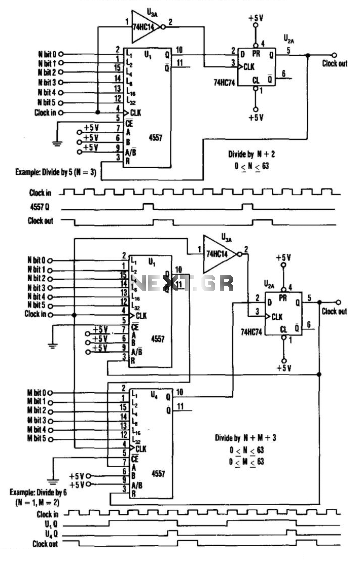
Programmable Frequency Divider
This divider utilizes a variable-length shift register, a type-D flip-flop, and an inverter. The clock signal is connected to the clock input of the flip-flop, while the output of the shift register is connected to the D input of the...
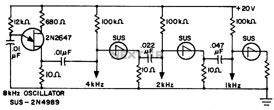
Frequency divider chain
The sawtooth output from each stage is one half the frequency of the preceding stage.
The described circuit features a multi-stage sawtooth waveform generator, where each stage produces an output with a frequency that is half of the frequency generated by...
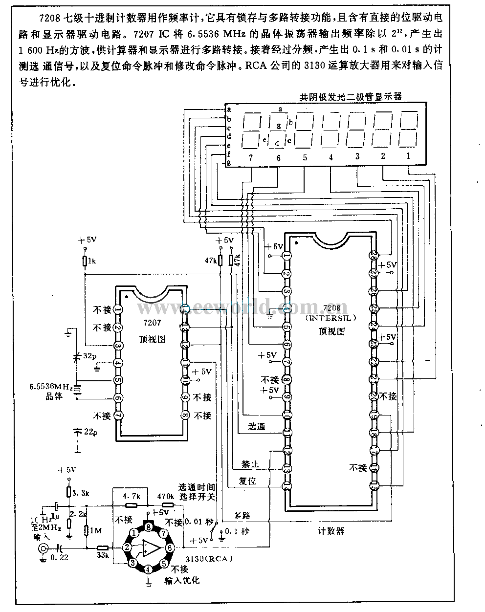
Frequency meter with 10Hz to 2MHz
The 7208 seven-metric system counter is utilized as a frequency meter. It features a latch and multiplexing function and incorporates a direct drive circuit along with a display driver circuit. The 7207 IC divides the output frequency of a 6.5536...
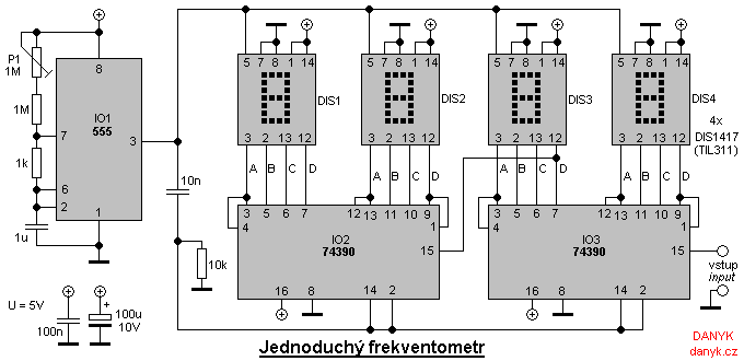
Simple digital frequency meter
A simple digital frequency meter has various applications, serving as an experiment for beginners, laboratory equipment, or a meter integrated into certain devices. It is ideal for situations where frequency measurement and digital display are required. The frequency meter is...
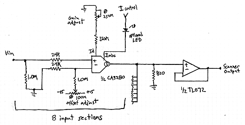
Interpolating Scanner Circuit
This design is for an interpolating scanner, a circuit featuring multiple signal inputs, a control voltage input, and a signal output. The output selectively transitions between inputs, smoothly fading from one to the next as the control voltage increases. A...