


2450MHz end-stage linear power amplifier configuration of the circuit diagram RF2126
#RF2126
#linear power amplifier
#2450MHz
#RF signal
#amplifier circuit
#end-stage
#radio frequency
#signal amplification
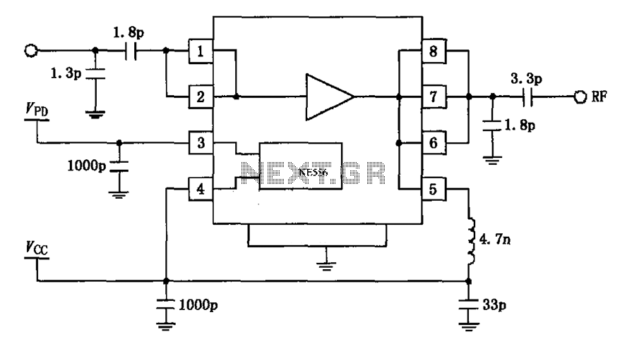
Description: The circuit depicted in the figure is based on the RF2126, a 2450 MHz end-stage linear power amplifier. The radio frequency (RF) signal enters through input pin 1 and is subsequently amplified by the amplifier stages (pins 5, 6, and 8). Input pin 1 is directly coupled to the internal amplifier, requiring a blocking coupling capacitor. This capacitor has a capacitance value ranging from 1.8 to 2.0 µF, and the input impedance at pin 1 is 50 ohms. The specified capacitance and inductance values are typical for operation at a frequency of 2450 MHz.
The RF2126 is designed for applications that demand high linearity and efficiency in the amplification of RF signals. The device operates within the 2.4 GHz ISM band, making it suitable for various wireless communication protocols. The amplifier's architecture typically includes multiple gain stages, enhancing signal strength while maintaining signal integrity.
The input stage, connected to pin 1, is critical for ensuring optimal signal transfer from the source to the amplifier. The blocking coupling capacitor serves to prevent DC voltage from affecting the signal path, thereby protecting the subsequent amplifier stages. The choice of a capacitor value between 1.8 µF and 2.0 µF is essential for matching the input impedance to the characteristic impedance of the RF signal, which is standardized at 50 ohms in many RF applications.
The output stages of the RF2126, represented by pins 5, 6, and 8, are designed to deliver the amplified RF signal to the load while minimizing distortion. The circuit layout should consider the transmission line effects and impedance matching to ensure maximum power transfer and minimize signal reflections. Proper grounding and decoupling techniques are also vital in maintaining the performance of the amplifier, especially at high frequencies.
In summary, the RF2126 amplifier circuit is a sophisticated design suitable for high-frequency applications, with careful attention paid to component selection and circuit layout to achieve reliable and efficient RF signal amplification. As shown in FIG constituted by RF2126 2450MHz end-stage linear power amplifier circuit. Radio frequency (RF) signal from the input pin 1, after amplified by the amplifier 7 fee t (5,6,8) output. Pin 1 is directly coupled to the internal amplifier, so a foot plus a blocking coupling capacitor. Blocking coupling capacitor has a capacity of 1.8 ~ 2.0 F, 1 foot input impedance of 50. Figure capacitance and inductance values are typical values 2450MHz frequency when.
The RF2126 is designed for applications that demand high linearity and efficiency in the amplification of RF signals. The device operates within the 2.4 GHz ISM band, making it suitable for various wireless communication protocols. The amplifier's architecture typically includes multiple gain stages, enhancing signal strength while maintaining signal integrity.
The input stage, connected to pin 1, is critical for ensuring optimal signal transfer from the source to the amplifier. The blocking coupling capacitor serves to prevent DC voltage from affecting the signal path, thereby protecting the subsequent amplifier stages. The choice of a capacitor value between 1.8 µF and 2.0 µF is essential for matching the input impedance to the characteristic impedance of the RF signal, which is standardized at 50 ohms in many RF applications.
The output stages of the RF2126, represented by pins 5, 6, and 8, are designed to deliver the amplified RF signal to the load while minimizing distortion. The circuit layout should consider the transmission line effects and impedance matching to ensure maximum power transfer and minimize signal reflections. Proper grounding and decoupling techniques are also vital in maintaining the performance of the amplifier, especially at high frequencies.
In summary, the RF2126 amplifier circuit is a sophisticated design suitable for high-frequency applications, with careful attention paid to component selection and circuit layout to achieve reliable and efficient RF signal amplification. As shown in FIG constituted by RF2126 2450MHz end-stage linear power amplifier circuit. Radio frequency (RF) signal from the input pin 1, after amplified by the amplifier 7 fee t (5,6,8) output. Pin 1 is directly coupled to the internal amplifier, so a foot plus a blocking coupling capacitor. Blocking coupling capacitor has a capacity of 1.8 ~ 2.0 F, 1 foot input impedance of 50. Figure capacitance and inductance values are typical values 2450MHz frequency when.

METAL DETECTOR
When the receiver is tuned to a medium wave radio station, feedback howl caused by the transmitter may occur when the coil and radio are positioned above or near a metal object. The search head is constructed from a margarine...
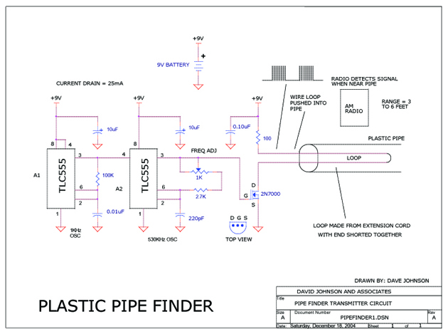
Plastic Pipe Finder
This circuit is designed to track the location of a plastic pipe buried underground. It transmits a weak RF signal that can be detected by a portable AM radio from a distance of approximately 6 feet.
The circuit operates by generating...
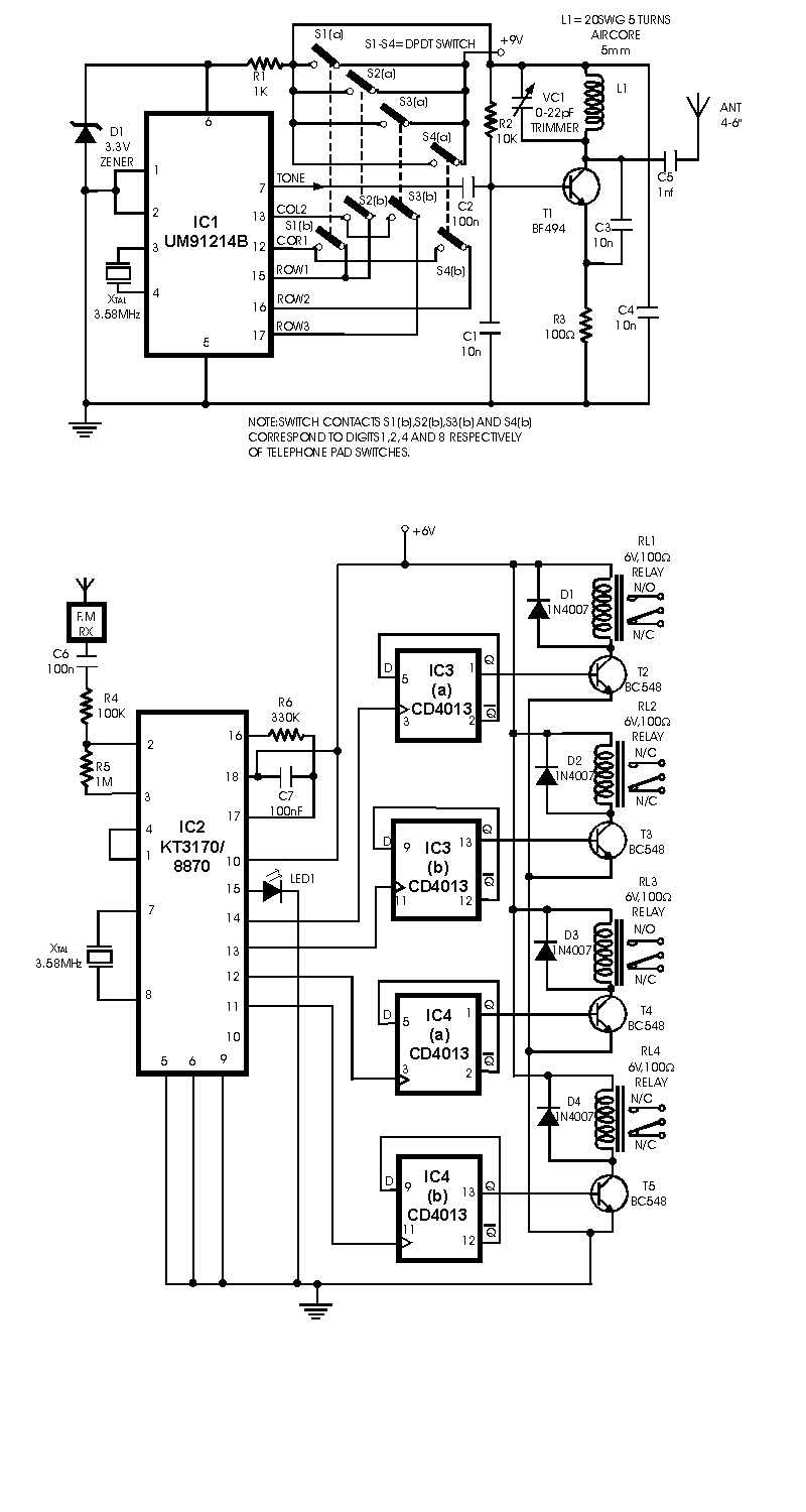
radio remote control
The circuit presented is a remote control unit that utilizes radio frequency signals to manage various electrical appliances. This remote control unit is designed with 4 channels but can be expanded to 12 channels. Its design is notable for its...
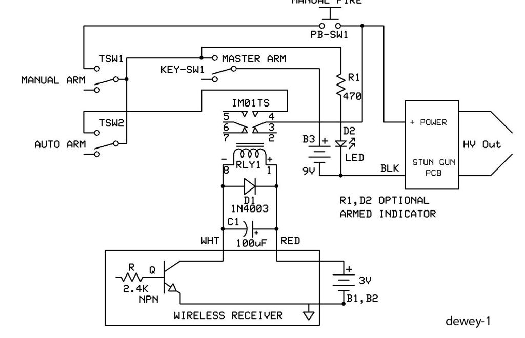
Remote Ignition System 100kv StunGun
This is a straightforward guide on creating an economical remote or wireless ignition system for a spud gun or similar applications. It employs a doorbell circuit to transmit a radio frequency (RF) signal to activate a relay, which completes a...
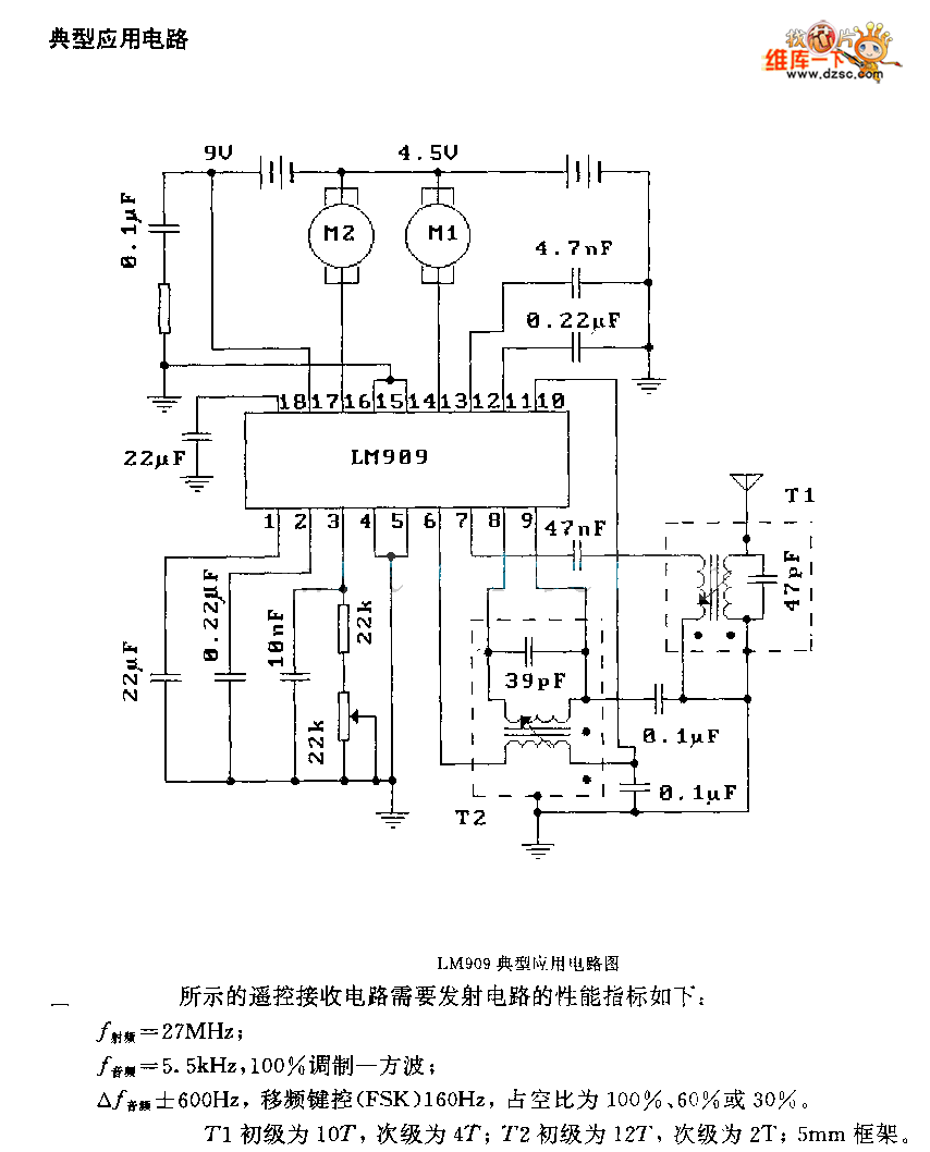
LM909 radio telecontrol receiving decoding circuit diagram
The performance indices of the telecontrol receiving decoding circuit are as follows: radio frequency (f) = 27 MHz, audio frequency (f) = 5.5 kHz, 100% modulation in square-wave form; radio frequency deviation is ±600 Hz, and the frequency shift keying...
LM909 radio telecontrol receiving decoding circuit diagram
The performance indices of the telecontrol receiving decoding circuit are as follows: radio frequency (f) = 27 MHz, audio frequency (f) = 5.5 kHz, 100% modulation in square-wave form; radio frequency deviation is ±600 Hz, and the frequency shift keying...
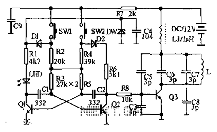
Dual AC radio remote control switch circuit diagram
The circuit diagram illustrates a dual radio remote control switch system. The transmitter section features Q3, which generates a high-frequency carrier signal, while Q1 and Q2 form the oscillator circuit. Pressing switch SW1 results in an oscillation frequency of 5...
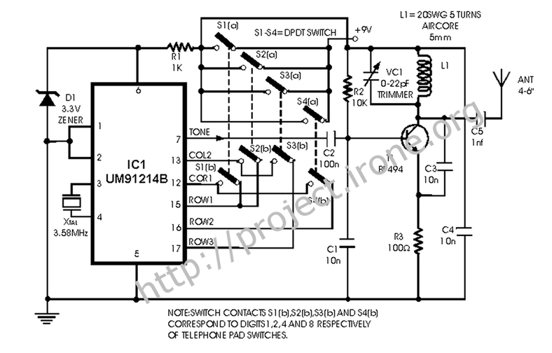
Radio frequency Of Remote Control
This is a remote control circuit that uses radio frequency electrical signals to control a variety of applications. Component: Transistor.
The remote control circuit operates by transmitting radio frequency (RF) signals to communicate with various devices. At its core, the circuit...
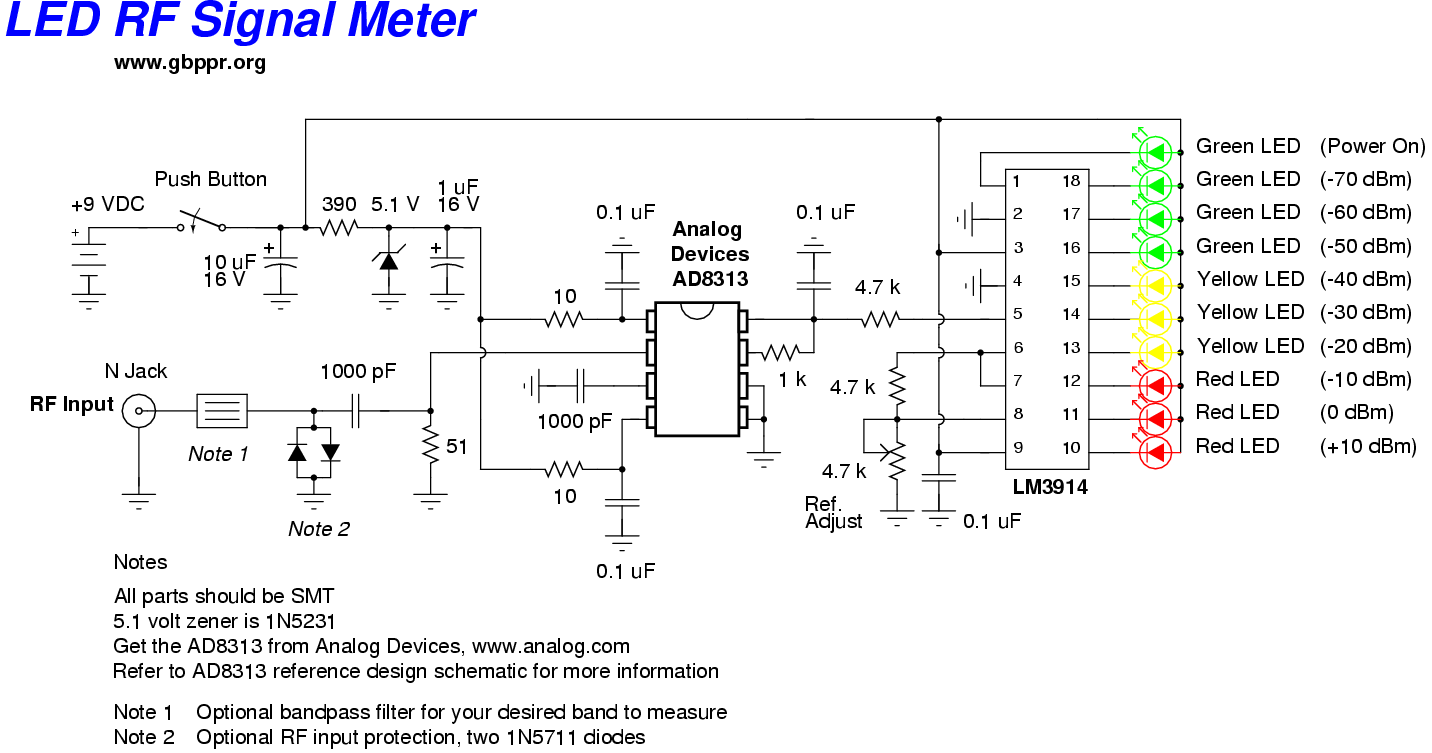
led rf signal meter
This RF Wave Absorption meter detects signals from 10 centimeters to 10 meters, depending on the setting of the 22 MegOhm gain adjustment potentiometer and the transmitter power. The RF signal is captured through germanium OA91 diodes and rectified to...