


27MHz crystal oscillator transmitter simulation in PSPICE
#27MHz
#crystal oscillator
#transmitter
#PSPICE
#simulation
#RF
#circuit design
#wireless communication
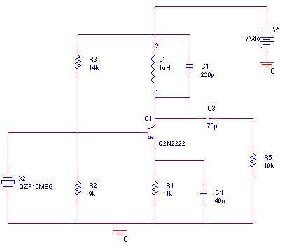
Description: A simulation of a 27 MHz transmitter circuit is to be conducted using PSPICE. The circuit diagram is provided as Figure 1 in the following content.
The 27 MHz transmitter circuit typically consists of several key components, including an oscillator, modulator, amplifier, and antenna. The oscillator generates a radio frequency signal at 27 MHz, which serves as the carrier wave for transmission. Commonly, a crystal oscillator or a phase-locked loop (PLL) circuit is employed to achieve stable frequency generation.
The modulator is responsible for encoding the information signal onto the carrier wave. This can be accomplished through amplitude modulation (AM), frequency modulation (FM), or phase modulation (PM), depending on the application requirements. The choice of modulation technique will influence the design of the modulator circuit, which may involve components such as operational amplifiers, diodes, and filters to shape the signal appropriately.
Following modulation, the signal is fed into a power amplifier, which increases the power level of the signal to ensure adequate transmission range. The amplifier circuit design should account for factors such as gain, linearity, and efficiency to maintain signal integrity while minimizing distortion.
Finally, the antenna is a critical component that converts the electrical signal into electromagnetic waves for transmission through the air. The design of the antenna, whether it be a dipole, monopole, or another type, should be matched to the transmitter's output impedance for optimal performance.
In PSPICE, the simulation can be set up by creating a schematic that incorporates these components. Each part of the circuit can be represented using appropriate models, and the simulation parameters can be adjusted to analyze the circuit's behavior under various conditions. The output can be visualized through waveform analysis, allowing for the evaluation of key performance metrics such as frequency stability, modulation fidelity, and transmission range.
By simulating the 27 MHz transmitter circuit in PSPICE, it is possible to identify potential issues and optimize the design before physical implementation, ensuring a more efficient and effective transmitter system.I want to simulate 27MHz transmitter circuit in PSPICE. Circuit diagram is given as Figure-1 in following..
The 27 MHz transmitter circuit typically consists of several key components, including an oscillator, modulator, amplifier, and antenna. The oscillator generates a radio frequency signal at 27 MHz, which serves as the carrier wave for transmission. Commonly, a crystal oscillator or a phase-locked loop (PLL) circuit is employed to achieve stable frequency generation.
The modulator is responsible for encoding the information signal onto the carrier wave. This can be accomplished through amplitude modulation (AM), frequency modulation (FM), or phase modulation (PM), depending on the application requirements. The choice of modulation technique will influence the design of the modulator circuit, which may involve components such as operational amplifiers, diodes, and filters to shape the signal appropriately.
Following modulation, the signal is fed into a power amplifier, which increases the power level of the signal to ensure adequate transmission range. The amplifier circuit design should account for factors such as gain, linearity, and efficiency to maintain signal integrity while minimizing distortion.
Finally, the antenna is a critical component that converts the electrical signal into electromagnetic waves for transmission through the air. The design of the antenna, whether it be a dipole, monopole, or another type, should be matched to the transmitter's output impedance for optimal performance.
In PSPICE, the simulation can be set up by creating a schematic that incorporates these components. Each part of the circuit can be represented using appropriate models, and the simulation parameters can be adjusted to analyze the circuit's behavior under various conditions. The output can be visualized through waveform analysis, allowing for the evaluation of key performance metrics such as frequency stability, modulation fidelity, and transmission range.
By simulating the 27 MHz transmitter circuit in PSPICE, it is possible to identify potential issues and optimize the design before physical implementation, ensuring a more efficient and effective transmitter system.I want to simulate 27MHz transmitter circuit in PSPICE. Circuit diagram is given as Figure-1 in following..
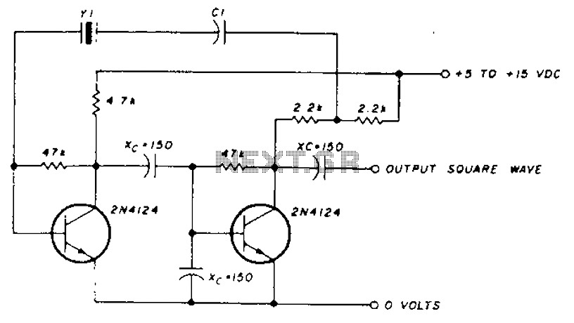
Frequency crystal oscillator circuit diagram of 10kHz-150kHz
A transistor in series with capacitor C1 can be utilized to adjust the oscillator output frequency. The frequency may vary with changes in capacitance ranging from 20 pF to 0.01 µF, or as determined by the tuning capacitor. The transistor...
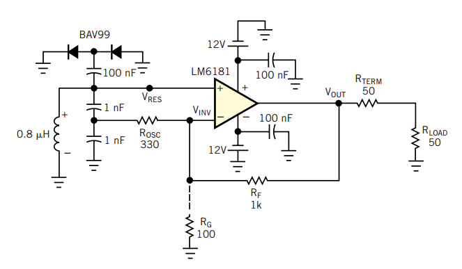
RF oscillator uses current-feedback op amp
A current-feedback amplifier is a well-known component with many uses. Its basic block diagram shows that its input stage is a voltage follower in practice, a symmetrical emitter follower. The configuration samples the output current, converts it to voltage across...
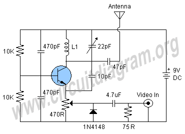
tv transmitter circuit
Here is a simple schematic of a TV transmitter circuit, or video transmitter circuit, capable of broadcasting in the VHF range from 60 to 200 MHz. The input video source can be any CCD camera or VCR. The output power...
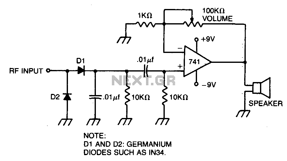
Modulation monitor
A broad-tuned receiver demodulates the RF signal picked up by a loosely coupled wire placed near the transmitting antenna.
The broad-tuned receiver operates by utilizing a loosely coupled wire antenna, which is strategically positioned in proximity to the transmitting antenna. This...
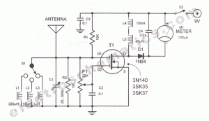
RF field strength meter circuit
A sensitive and reliable RF field strength meter is an invaluable instrument in amateur radio and in the radio-controlled model area. A field strength meter is.
A radio frequency (RF) field strength meter is a specialized device used to measure the...
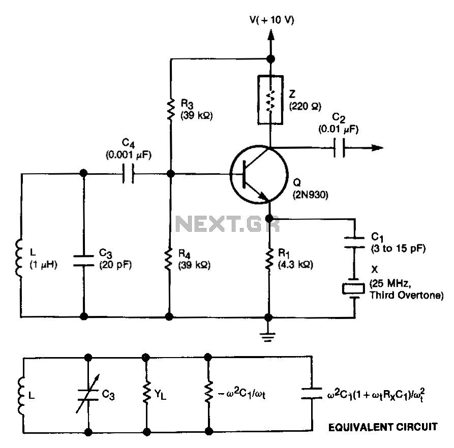
Crystal-controlled-reflection-oscillator
This unit is easily tunable and stable, consumes minimal power, and is more cost-effective than other types of oscillators that operate at similar frequencies. This unique combination of features is made possible by a design concept that involves operating the...
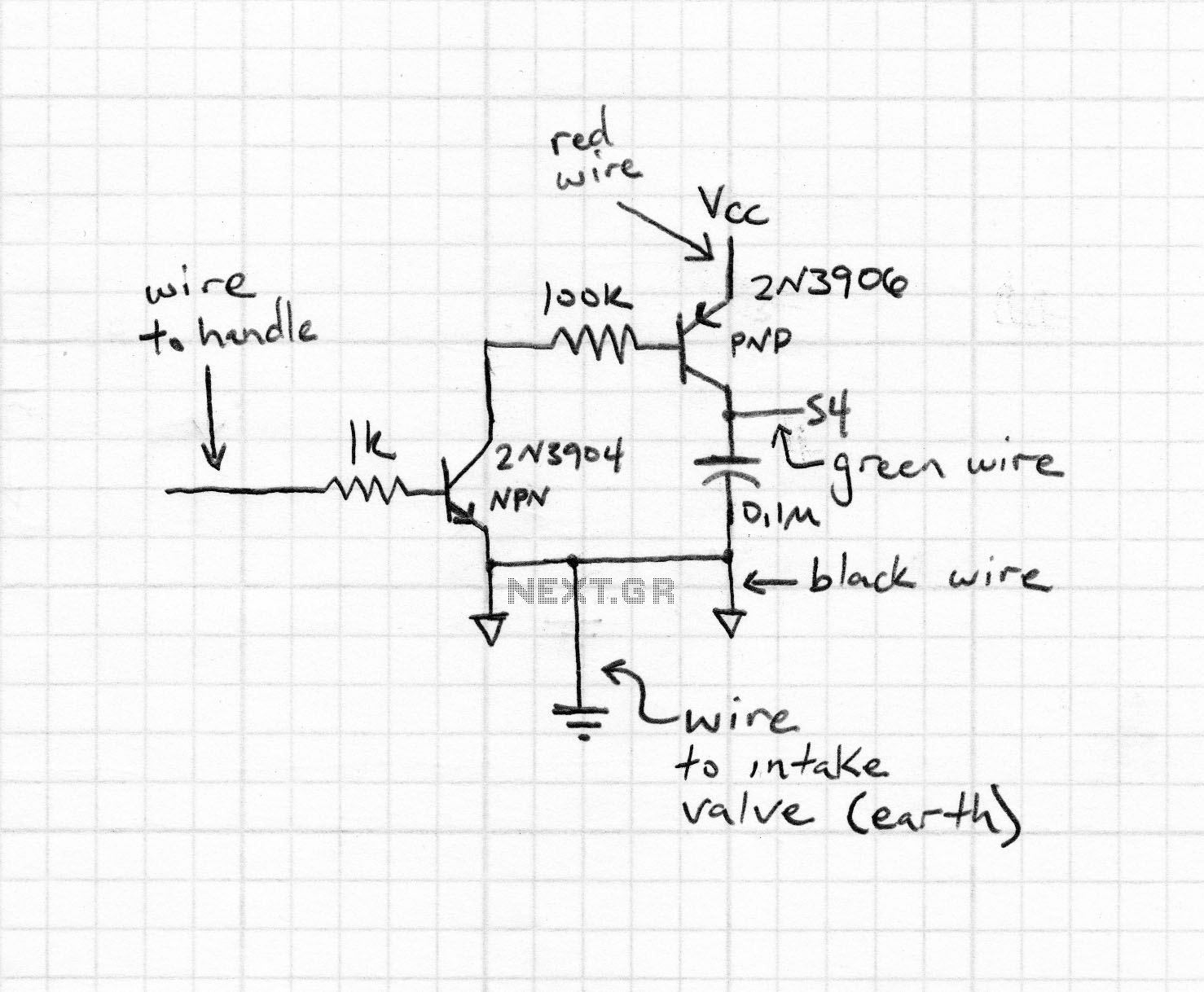
RF field strength meter
A simple Field Strength Meter consists of a small antenna, a detector diode, a resistor, a capacitor, and a micro ammeter. This circuit is sensitive enough to detect HF fields when positioned close to the transmitting antenna. The circuit functioned...
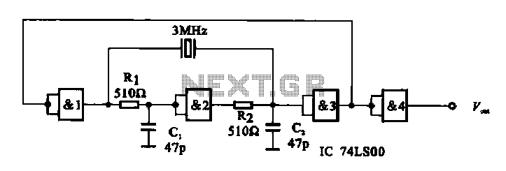
E crystal oscillator circuit composed of several gates
A crystal oscillator circuit is composed of several gates. Figure (A) illustrates a crystal oscillator circuit operating at 1 MHz, while Figure (B) depicts a 20 MHz crystal oscillator circuit. Figure (C) represents a variable crystal oscillator circuit with a...
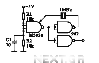
Crystal oscillator DTL integrated circuit
A crystal oscillator is implemented using a DTL (Diode-Transistor Logic) integrated circuit. The oscillation frequencies are 100 kHz and 1 MHz. The circuit consists of a gate circuit that generates a signal for the oscillator circuitry in DTL.
The crystal oscillator...