


330 MHz prescaler for AVR frequency meter
#prescaler
#frequency meter
#AVR
#MM74HC6040
#MCT12080
#MCT10290
#ripple counter
#sine wave
#square wave
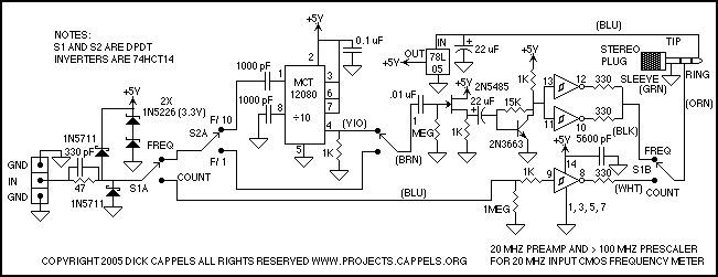
Description: These parameters are expected with an approximately 50% square wave up to frequencies of several MHz, and symmetric sine waves at higher frequencies. The primary limitation is based on the maximum clocking rate specification for the MM74HC6040 ripple counter in use in the Slightly More Serious Frequency Meter project. Selection of faster parts and careful circuit layout can extend the upper limit of the useful frequency range. The lower frequency limit is the lowest sine wave input frequency for the MCT12080 at which the input of the MCT10290 does not oscillate. More: Schmitt trigger buffer that then sends the signal on to the counter.
Regardless of how the signal is routed, it must first pass through an input protection network, which includes two Schottky diodes and a Zener clamp. The 1N5711 Schottky diodes prevent the input signal from going more than a Schottky diode drop below ground or above the power supply. Schottky diodes are used due to their lower voltage drop compared to the PN protection diodes in the CMOS integrated circuit they are intended to protect, allowing them to draw more current from excessive input voltages than the input protection diodes in the integrated circuits.
The two 1N5226 Zener diodes in series prevent the power supply from rising above 6.6 volts in case the input is accidentally connected to a low impedance source that is higher than 5 volts. A 47 Ohm resistor limits the input current in case of excessive voltage being applied to the inputs.
The input of the frequency meter requires a full 5-volt CMOS logic swing, and the prescaler's output is less than 1 volt peak-to-peak. Therefore, when the prescaler is switched into the circuit, the signal goes through the prescaler, then the preamp, which drives the frequency meter through the Schmitt trigger buffers.
The MCT10280 prescaler can be set to divide by 80, 40, 20, or 10, depending on which pins are tied to the power supply. A division factor of 10 is selected as it suffices for the intended application, simplifying mental calculations for the meter reading. However, a notable issue with the MCT10280 is that if it does not receive an adequate input, the output can be very noisy, resulting in erroneous counts in the couple MHz range on the frequency meter. This noise occurs when the signal amplitude or frequency is too low, hence the prescaler is intended for use with inputs ranging from 10 MHz to 300 MHz.
Regardless of the division factor, the signal must pass through the preamp. In the preamp stage, a 2N5485 N-channel FET is configured as a source follower, providing high input impedance to the input signal while driving the subsequent stage, a 2N3663 limiting amplifier, with a low impedance signal, yielding high AC gain.
The output from the 2N3663 consists of clean square waves with fast rise and fall times. When interfacing with the 74HCT02 input on the frequency meter, care must be taken to avoid oscillation at the input. To mitigate this risk, the signal is routed through a 74HCT14 Schmitt trigger. The cable carrying the signal has an impedance of approximately 150 ohms, necessitating the use of two 300-ohm resistors in parallel to minimize ringing at the frequency meter end of the cable. No termination is applied at the frequency meter end, as it would diminish the signal amplitude below the CMOS thresholds.
Power for the entire circuit is supplied via the cable and is regulated by a 78L05 voltage regulator, ensuring stable operation across the various components involved in the frequency measurement process.These parameters are expected with an approximately 50% square wave up to frequencies of seveal MHz, and symmetric sine waves at higher frequencies. The primary limitation is based on the maximum clocking rate specification for the MM74HC6040 ripple counter in use in the Slightly More Serious Frequency Meter project.
Selection of faster parts and careful circuit layout can extend the upper limit of the useful frequency range. The lower frequency imit is the lowest sine wave input frequency for the MCT12080 at which the input of the MCT10290 does not osccilate.
Schmitt trigger buffer that then sends the signal on to the counter. Regardless of how the signal is routed, it must first pass through an input protection network, which includes two schottky diodes and a zener clamp. The 1N5711 schottky diodes prevent the input signal from going more than a schottky diode drop below ground or above the power supply.
I used Schottky diodes because they have a lower voltage drop than the PN protection diodes on the CMOS integrated circuit they are intended to protect, and as such, they will draw much more of the current from excessive input voltages than the input protection diodes in the integrated circuits. The two 1N5226 zener diodes in series prevents the power supply from rising above 6.6 volts in case the input is accidentally connected to a low impedance source that is higher than 5 volts.
The 47 Ohm resistor limits the input current in case of excessive voltage being applied to the inputs. The input of the frequency meter requires a full 5 volt CMOS logic swing, and the prescaler's output is less than 1 volt peak-to-peak, so the prescaler, when switched into the circuit, the signal goes through the prescaler, then the preamp, and the preamp drives the frequency meter through the Schmidt trigger buffers.
The MCT10280 prescaler can be set to divide by 80, 40, 20, or 10, as a function of which pins are tied to the power supply. I set this one to divide by 10 since it is adequate for my needs, and the mental calculation of multiplying the meter reading by 10 is not taxing.
One problem with the MCT10280 is that if it doesn't have an adequate input, the output is very noisy, which shows up as counts in the couple MHz range on the frequency meter. This noise shows up if the signal amplitude the signal frequency is too low. For this reason, I only intend to use the prescaler with inputs between 10 MHz and 300 MHz. Whether the signal is divided by ten or not, it must pass through the preamp. In the Preamp, a 2N5485 N-channel FET is connected as a source follower. This provides a high input impedance to the input signal and drives the next stage, the 2N3663 limiting amplifier with a nice low impedance signal.
This results in high AC gain. DC buffer Signals from the 2N3663 are nice, clean square waves with fast rise and fall times, and when driving the 74HCT02 input on the frequency meter, could result in the input of the 74HCT02 oscillating. To prevent this, the signal is passed through a 74HCT14 Schmitt trigger. The signal conductor in the cable has an impedance of about 150 ohms, so it is driven through two 300 ohm resistors in parallel to keep the ringing on the frequency meter end of the cable to a tolerable level.
There is no termination on the frequency meter end of the cable because terminating it would reduce the amplitude of the signal below the CMOS thresholds. Power for all the circuit comes through the cable and is regulated by the 78L05 regulator.
Regardless of how the signal is routed, it must first pass through an input protection network, which includes two Schottky diodes and a Zener clamp. The 1N5711 Schottky diodes prevent the input signal from going more than a Schottky diode drop below ground or above the power supply. Schottky diodes are used due to their lower voltage drop compared to the PN protection diodes in the CMOS integrated circuit they are intended to protect, allowing them to draw more current from excessive input voltages than the input protection diodes in the integrated circuits.
The two 1N5226 Zener diodes in series prevent the power supply from rising above 6.6 volts in case the input is accidentally connected to a low impedance source that is higher than 5 volts. A 47 Ohm resistor limits the input current in case of excessive voltage being applied to the inputs.
The input of the frequency meter requires a full 5-volt CMOS logic swing, and the prescaler's output is less than 1 volt peak-to-peak. Therefore, when the prescaler is switched into the circuit, the signal goes through the prescaler, then the preamp, which drives the frequency meter through the Schmitt trigger buffers.
The MCT10280 prescaler can be set to divide by 80, 40, 20, or 10, depending on which pins are tied to the power supply. A division factor of 10 is selected as it suffices for the intended application, simplifying mental calculations for the meter reading. However, a notable issue with the MCT10280 is that if it does not receive an adequate input, the output can be very noisy, resulting in erroneous counts in the couple MHz range on the frequency meter. This noise occurs when the signal amplitude or frequency is too low, hence the prescaler is intended for use with inputs ranging from 10 MHz to 300 MHz.
Regardless of the division factor, the signal must pass through the preamp. In the preamp stage, a 2N5485 N-channel FET is configured as a source follower, providing high input impedance to the input signal while driving the subsequent stage, a 2N3663 limiting amplifier, with a low impedance signal, yielding high AC gain.
The output from the 2N3663 consists of clean square waves with fast rise and fall times. When interfacing with the 74HCT02 input on the frequency meter, care must be taken to avoid oscillation at the input. To mitigate this risk, the signal is routed through a 74HCT14 Schmitt trigger. The cable carrying the signal has an impedance of approximately 150 ohms, necessitating the use of two 300-ohm resistors in parallel to minimize ringing at the frequency meter end of the cable. No termination is applied at the frequency meter end, as it would diminish the signal amplitude below the CMOS thresholds.
Power for the entire circuit is supplied via the cable and is regulated by a 78L05 voltage regulator, ensuring stable operation across the various components involved in the frequency measurement process.These parameters are expected with an approximately 50% square wave up to frequencies of seveal MHz, and symmetric sine waves at higher frequencies. The primary limitation is based on the maximum clocking rate specification for the MM74HC6040 ripple counter in use in the Slightly More Serious Frequency Meter project.
Selection of faster parts and careful circuit layout can extend the upper limit of the useful frequency range. The lower frequency imit is the lowest sine wave input frequency for the MCT12080 at which the input of the MCT10290 does not osccilate.
Schmitt trigger buffer that then sends the signal on to the counter. Regardless of how the signal is routed, it must first pass through an input protection network, which includes two schottky diodes and a zener clamp. The 1N5711 schottky diodes prevent the input signal from going more than a schottky diode drop below ground or above the power supply.
I used Schottky diodes because they have a lower voltage drop than the PN protection diodes on the CMOS integrated circuit they are intended to protect, and as such, they will draw much more of the current from excessive input voltages than the input protection diodes in the integrated circuits. The two 1N5226 zener diodes in series prevents the power supply from rising above 6.6 volts in case the input is accidentally connected to a low impedance source that is higher than 5 volts.
The 47 Ohm resistor limits the input current in case of excessive voltage being applied to the inputs. The input of the frequency meter requires a full 5 volt CMOS logic swing, and the prescaler's output is less than 1 volt peak-to-peak, so the prescaler, when switched into the circuit, the signal goes through the prescaler, then the preamp, and the preamp drives the frequency meter through the Schmidt trigger buffers.
The MCT10280 prescaler can be set to divide by 80, 40, 20, or 10, as a function of which pins are tied to the power supply. I set this one to divide by 10 since it is adequate for my needs, and the mental calculation of multiplying the meter reading by 10 is not taxing.
One problem with the MCT10280 is that if it doesn't have an adequate input, the output is very noisy, which shows up as counts in the couple MHz range on the frequency meter. This noise shows up if the signal amplitude the signal frequency is too low. For this reason, I only intend to use the prescaler with inputs between 10 MHz and 300 MHz. Whether the signal is divided by ten or not, it must pass through the preamp. In the Preamp, a 2N5485 N-channel FET is connected as a source follower. This provides a high input impedance to the input signal and drives the next stage, the 2N3663 limiting amplifier with a nice low impedance signal.
This results in high AC gain. DC buffer Signals from the 2N3663 are nice, clean square waves with fast rise and fall times, and when driving the 74HCT02 input on the frequency meter, could result in the input of the 74HCT02 oscillating. To prevent this, the signal is passed through a 74HCT14 Schmitt trigger. The signal conductor in the cable has an impedance of about 150 ohms, so it is driven through two 300 ohm resistors in parallel to keep the ringing on the frequency meter end of the cable to a tolerable level.
There is no termination on the frequency meter end of the cable because terminating it would reduce the amplitude of the signal below the CMOS thresholds. Power for all the circuit comes through the cable and is regulated by the 78L05 regulator.
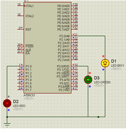
SQUARE WAVE GENERATOR EMBEDDED C
A common requirement across various applications is a continuous signal source that produces a regular and definable waveform. Among these waveforms, the square wave is particularly significant. The circuit described utilizes a comparator featuring both positive and negative feedback to...
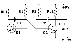
square wave generator
An electronic project to build a multivibrator as a basic first test instrument, ideal for troubleshooting radio repairs. Includes a how-to-use guide. An excellent beginner project.
The multivibrator circuit serves as a fundamental building block in electronics, providing a versatile tool...
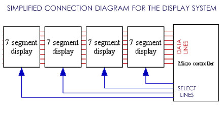
5hz to 500 Khz Frequency-Meter
Based on the AT89C52 microcontroller, this 500 kHz frequency meter is designed for tracing and debugging circuits, adjusting the frequency of 555 timers, and performing various frequency measurements in digital circuits. Once this tool is in hand, it becomes indispensable...
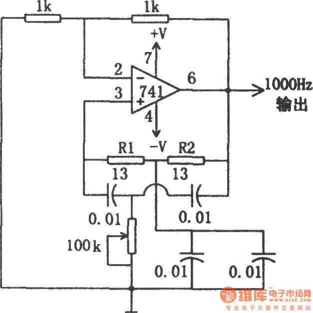
1kHz sine wave oscillator(741)
The circuit illustrated in the diagram is a 1 kHz sine wave oscillator circuit. Based on a double-T circuit configuration, it utilizes a standard 741 operational amplifier to generate a 1000 Hz sine wave output. The circuit begins oscillation when...
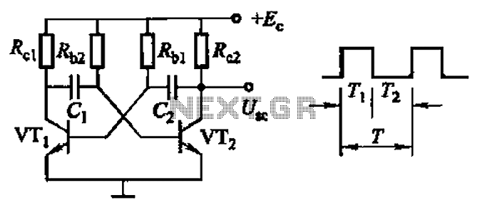
Common non-sinusoidal oscillator circuit waveform square wave oscillator self-excited multivibrator
Common non-sinusoidal oscillator circuit, waveform and frequency formula - square wave oscillator - self-excited multivibrator
The common non-sinusoidal oscillator circuit, specifically the square wave oscillator, is a fundamental electronic circuit utilized to generate square wave signals. It operates based on the...
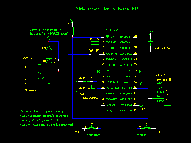
avr usb slideshow presenter.
USB HID is a specification that encompasses devices such as mice and keyboards. It features a GPL-based driver that allows the implementation of USB on an AVR microcontroller without the need for specialized hardware. Additionally, there is the AVR309 software...
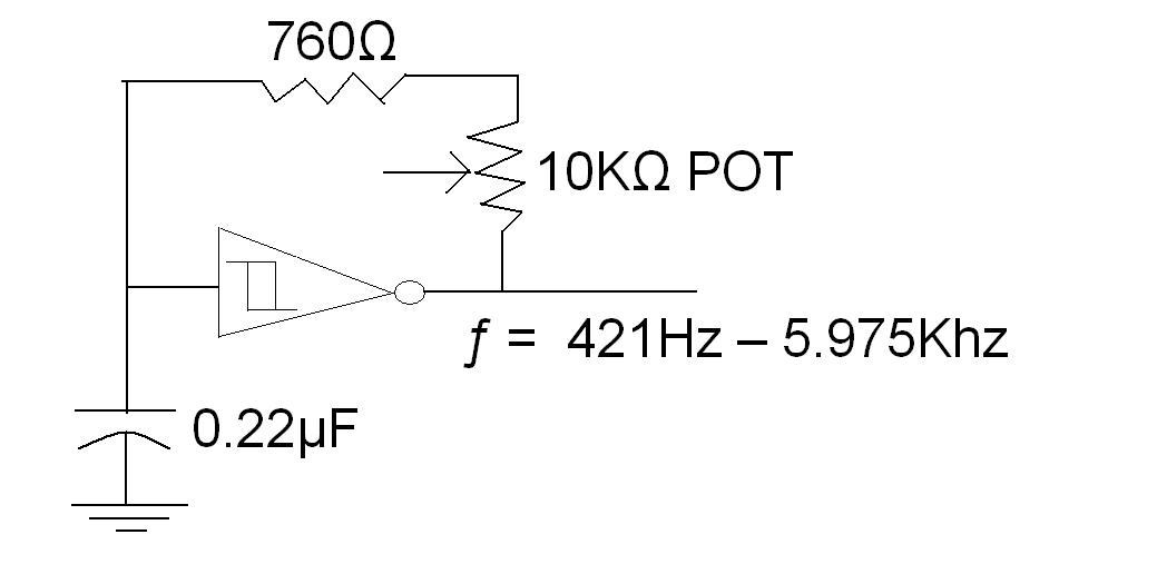
square wave 2 sine wave convertion
A TTL square wave needs to be converted into a sine wave, with a frequency range of 4Hz to 60Hz. One method to achieve this is by filtering the square wave using a high-order filter. However, if the frequency varies,...
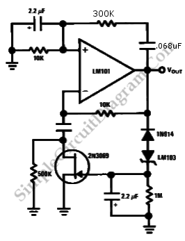
Wien Bridge Sine Wave Oscillator
Achieving the appropriate amplifier loop gain is a significant challenge in generating a low distortion, constant amplitude sine wave. Nevertheless, this issue can be addressed with...
Amplifier loop gain is a critical parameter in the design of audio and signal processing...
AVR robots
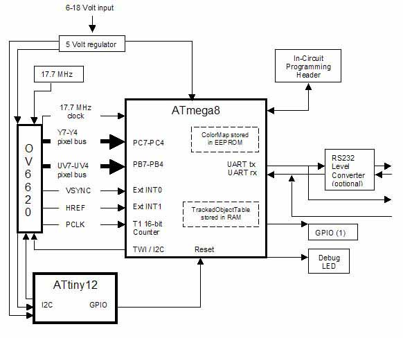
The line is intentionally not straight to test its performance with zig-zags and splits, which are common in the Chibots advanced line-following contest. The AVRcam is a compact, real-time image processing engine designed to track colorful objects. This system is...