


50 impedance RF2320 linear amplification circuit diagram
#RF2320
#linear amplifier
#50 ohm impedance
#transmission line
#matching network
#inductive
#capacitive
#RF amplification
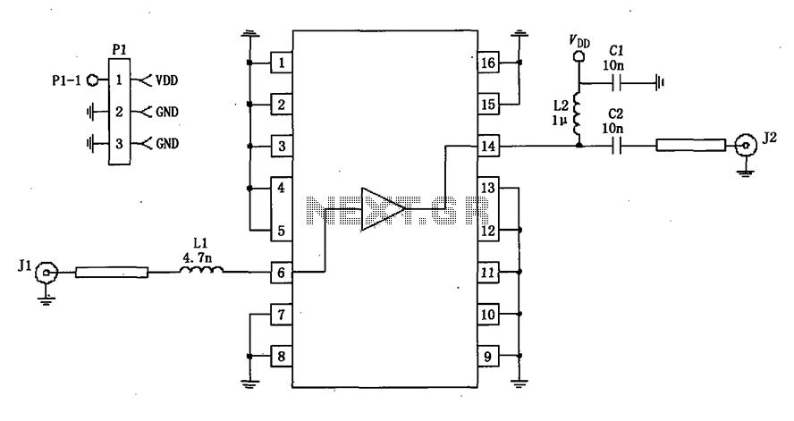
Description: A 50-ohm impedance is illustrated in the RF2320 linear amplifier circuit, which is configured for input and output using transmission lines and inductive or capacitive components to create a matching network.
The RF2320 linear amplifier circuit is designed to operate with a 50-ohm impedance, which is a standard value in RF applications, ensuring optimal power transfer and minimal signal reflection. The input and output stages of the amplifier utilize transmission lines, which are critical for maintaining signal integrity and minimizing losses. These transmission lines can be implemented using microstrip or stripline technologies, depending on the PCB design and the desired frequency characteristics.
The matching network is an essential component in this circuit, as it ensures that the amplifier is properly matched to the source and load impedances. This matching can be achieved through the use of inductive or capacitive components, which can be configured in various ways, such as L-networks, T-networks, or π-networks, depending on the specific requirements of the application. The choice of components and their values will depend on the frequency of operation and the specific characteristics of the RF2320 amplifier.
Properly designing the matching network involves calculating the necessary component values to achieve the desired impedance transformation. This can be accomplished using techniques such as Smith chart analysis or computer-aided design (CAD) tools to simulate the circuit performance. The goal is to achieve a flat frequency response over the desired bandwidth while maintaining low insertion loss and high return loss.
In summary, the RF2320 linear amplifier circuit, with its 50-ohm impedance configuration, effectively utilizes transmission lines and matching networks to optimize performance for RF applications. The careful selection and arrangement of inductive and capacitive components are crucial for achieving the desired operational characteristics.50 impedance as shown in Figure grounds RF2320 linear amplifier circuit configured, input, output, using the transmission line and inductive or capacitive constitute matching n etwork.
The RF2320 linear amplifier circuit is designed to operate with a 50-ohm impedance, which is a standard value in RF applications, ensuring optimal power transfer and minimal signal reflection. The input and output stages of the amplifier utilize transmission lines, which are critical for maintaining signal integrity and minimizing losses. These transmission lines can be implemented using microstrip or stripline technologies, depending on the PCB design and the desired frequency characteristics.
The matching network is an essential component in this circuit, as it ensures that the amplifier is properly matched to the source and load impedances. This matching can be achieved through the use of inductive or capacitive components, which can be configured in various ways, such as L-networks, T-networks, or π-networks, depending on the specific requirements of the application. The choice of components and their values will depend on the frequency of operation and the specific characteristics of the RF2320 amplifier.
Properly designing the matching network involves calculating the necessary component values to achieve the desired impedance transformation. This can be accomplished using techniques such as Smith chart analysis or computer-aided design (CAD) tools to simulate the circuit performance. The goal is to achieve a flat frequency response over the desired bandwidth while maintaining low insertion loss and high return loss.
In summary, the RF2320 linear amplifier circuit, with its 50-ohm impedance configuration, effectively utilizes transmission lines and matching networks to optimize performance for RF applications. The careful selection and arrangement of inductive and capacitive components are crucial for achieving the desired operational characteristics.50 impedance as shown in Figure grounds RF2320 linear amplifier circuit configured, input, output, using the transmission line and inductive or capacitive constitute matching n etwork.
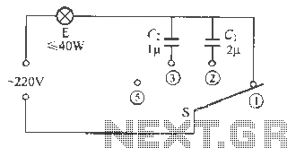
Capacitive Dimmer switch circuit
The capacitive dimmer switch circuit is illustrated in Figure 9. It operates based on the principle of capacitive reactance with alternating current. When the switch is in the position shown, the normal light bulb operates at maximum brightness. When the...
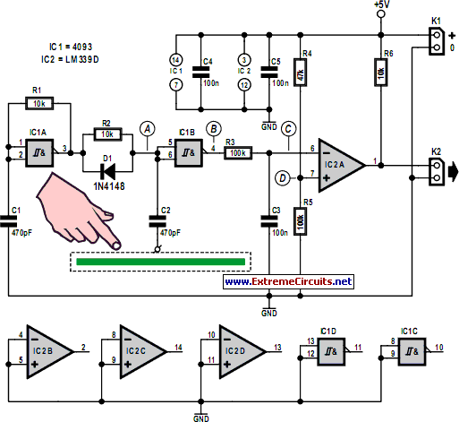
simple capacitive touch sensor
Capacitive touch sensors operate based on the electrical capacitance associated with the human body. When a finger approaches the sensor, it establishes a capacitance to the ground, typically ranging from 30 to 100 pF. This phenomenon can be utilized for...
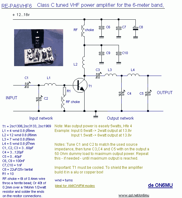
Linear amplifier
10W HF linear amplifier circuit schematics free electronic circuits diagram wiring design plans schema DIY projects handbook guide tutorial schematic electronic schematic diagram project electronic schematic circuit diagram.
The 10W HF linear amplifier circuit is designed to amplify high-frequency signals with...
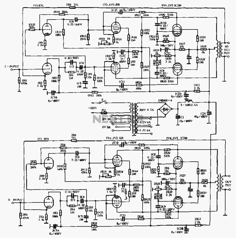
60W x2 standard linear type tube amplifiers
A standard linear amplifier is designed according to a conventional circuit configuration, with the power of the beam tube indicated in Figure 1-8. The output stage employs power tubes such as EL34, KT88, and KT100, which are types of radio...
.jpg "Inductive Proximity Sensors circuit")
Inductive Proximity Sensors
The inductive sensor is a straightforward device at its core. It consists of a coil of wire with an electric current flowing through it. This sensor primarily ignores most objects that come close to the coil. However, when a metallic...
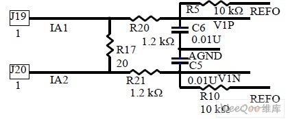
Design and realizing of the electric transmission line monitoring system
Observing and addressing the phase adjustment issues in electric transmission lines manually poses significant challenges, particularly in recording and normalizing three major problems. This design encompasses both software and hardware components, developed over an extended period. It is intended to...
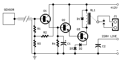
capacitive sensor
For proper operation, the circuit ground must be connected via a small-value, high-voltage-rated capacitor to one side of the mains supply socket. The "Live" side is the right one. This circuit is designed to animate shop windows using a capacitive...
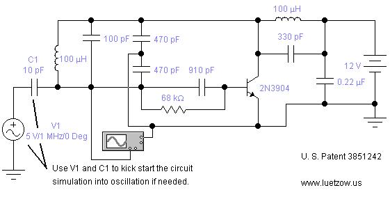
Inductive Electronic Oscillator Circuit
The oscillator circuits presented on this page are derived from expired or non-maintained U.S. Patents. All circuits are formatted for "Electronic Workbench 5.12" or "Multisim 7" circuit simulation software. A note regarding SPICE simulation of electronic oscillator circuits: all the...
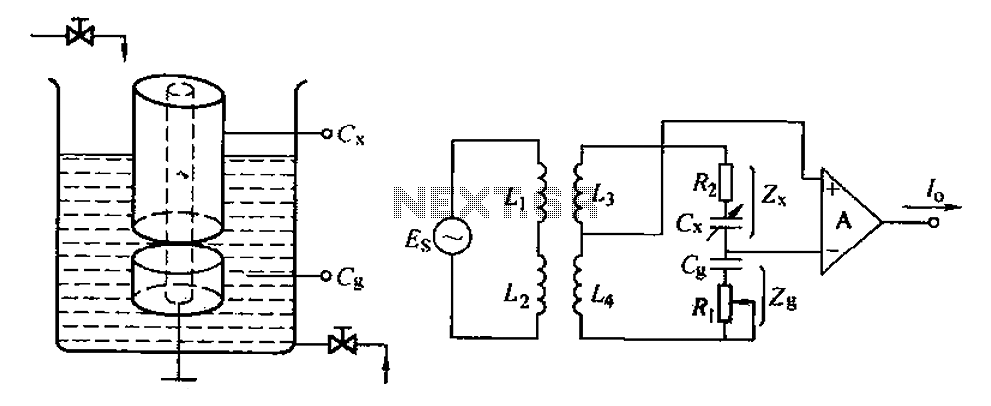
Capacitive level measuring circuit
The capacitance change in a capacitive sensor is directly converted into electrical parameters, which are then unified for signal transmission, processing, and display. These electrical parameters can be categorized into resistive, capacitive, and inductive types. This explanation focuses on capacitive...