


550 to 1100 KHz AM Receiver Circuit
#AM receiver
#550-1100 KHz
#sensitivity adjustment
#selectivity adjustment
#radio circuit
#tuning
#RF
#amplitude modulation
#receiver design
#broadcast
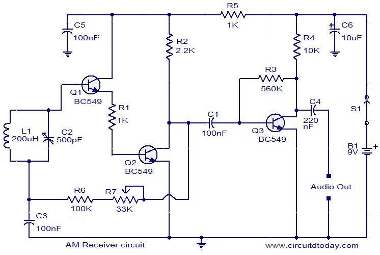
Description: The following circuit illustrates an AM receiver capable of operating within the frequency range of 550 to 1100 KHz. Features include adjustments for sensitivity and selectivity of the circuit.
The AM receiver circuit designed for the frequency range of 550 to 1100 KHz typically consists of several key components that work together to demodulate amplitude-modulated signals. The primary components include an antenna, a radio frequency (RF) amplifier, a mixer, a local oscillator, a demodulator, and an audio amplifier.
The antenna captures the incoming radio waves, converting them into electrical signals. These signals are then fed into the RF amplifier, which amplifies the weak signals to a level suitable for further processing. The RF amplifier may employ transistors or operational amplifiers to enhance the signal strength while minimizing noise.
Following amplification, the signals are mixed with a local oscillator signal in the mixer stage. The local oscillator generates a frequency that allows the desired signal to be down-converted to an intermediate frequency (IF), typically around 455 KHz for AM receivers. This process enables better filtering and amplification of the desired signal while rejecting unwanted frequencies.
The demodulator then extracts the audio information from the modulated carrier wave. This can be accomplished using various techniques, such as envelope detection or synchronous detection. Envelope detection is the most common method used in simple AM receivers, where the amplitude variations of the incoming signal are directly translated into audio signals.
After demodulation, the audio signal is often weak and requires further amplification. An audio amplifier is employed to boost the audio signal to a level suitable for driving speakers or headphones. This stage may include additional filtering to enhance sound quality and remove any remaining high-frequency components.
To enhance the performance of the AM receiver, components such as variable capacitors and inductors may be included to allow for tuning and adjustment of sensitivity and selectivity. These adjustments enable the user to optimize the circuit for specific stations and improve overall reception quality.
In summary, the AM receiver circuit operating between 550 and 1100 KHz is a complex assembly of components that work together to receive, amplify, demodulate, and output audio signals from amplitude-modulated radio transmissions. The ability to adjust sensitivity and selectivity is crucial for effective operation in varying radio environments.The following circuit shows about 550 to 1100 KHz AM Receiver Circuit. Features: used to adjust the sensitivity and selectivity of the circuit, ..
The AM receiver circuit designed for the frequency range of 550 to 1100 KHz typically consists of several key components that work together to demodulate amplitude-modulated signals. The primary components include an antenna, a radio frequency (RF) amplifier, a mixer, a local oscillator, a demodulator, and an audio amplifier.
The antenna captures the incoming radio waves, converting them into electrical signals. These signals are then fed into the RF amplifier, which amplifies the weak signals to a level suitable for further processing. The RF amplifier may employ transistors or operational amplifiers to enhance the signal strength while minimizing noise.
Following amplification, the signals are mixed with a local oscillator signal in the mixer stage. The local oscillator generates a frequency that allows the desired signal to be down-converted to an intermediate frequency (IF), typically around 455 KHz for AM receivers. This process enables better filtering and amplification of the desired signal while rejecting unwanted frequencies.
The demodulator then extracts the audio information from the modulated carrier wave. This can be accomplished using various techniques, such as envelope detection or synchronous detection. Envelope detection is the most common method used in simple AM receivers, where the amplitude variations of the incoming signal are directly translated into audio signals.
After demodulation, the audio signal is often weak and requires further amplification. An audio amplifier is employed to boost the audio signal to a level suitable for driving speakers or headphones. This stage may include additional filtering to enhance sound quality and remove any remaining high-frequency components.
To enhance the performance of the AM receiver, components such as variable capacitors and inductors may be included to allow for tuning and adjustment of sensitivity and selectivity. These adjustments enable the user to optimize the circuit for specific stations and improve overall reception quality.
In summary, the AM receiver circuit operating between 550 and 1100 KHz is a complex assembly of components that work together to receive, amplify, demodulate, and output audio signals from amplitude-modulated radio transmissions. The ability to adjust sensitivity and selectivity is crucial for effective operation in varying radio environments.The following circuit shows about 550 to 1100 KHz AM Receiver Circuit. Features: used to adjust the sensitivity and selectivity of the circuit, ..
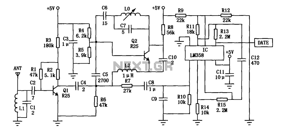
DF data transmission module and the super-regenerative receiver module
The DF data transmission module operates at a frequency of 315 MHz and utilizes a surface acoustic wave (SAW) resonator for frequency stabilization, ensuring high frequency stability. The frequency drift remains minimal, at only 3 x 10^-6, across a temperature...
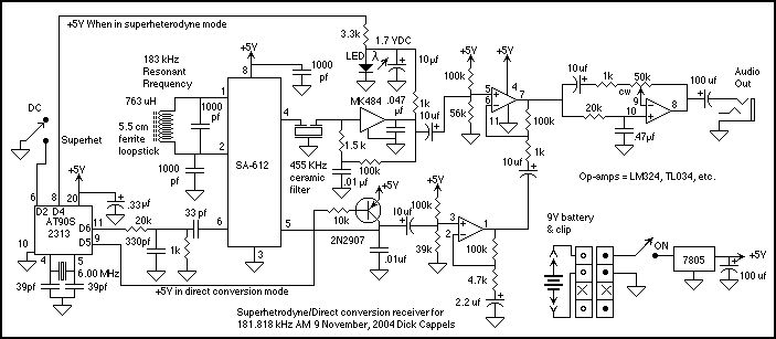
AM receiver
This is a description of an experimental AM receiver for VLF. It is crystal controlled to receive 181.818 kHz (more or less) and operates as either a single conversion superhetrodyne or a direct conversion receiver. The bandwidths are expected to...
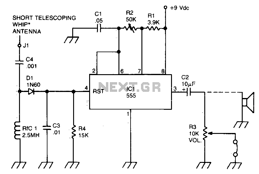
RF-powered sidetone oscillator
A sidetone oscillator is a specific type of audio astable multivibrator. Keying is achieved by turning the oscillator on and off through the application of a positive DC potential, which is generated from the RF signal to the reset terminal...
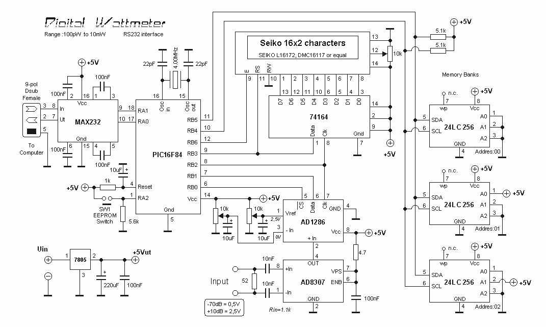
RF Digital Wattmeter
The power is measured by the circuit AD8307 over a 50 ohm dummy load. An A/D converter of 12 bit converts the analog output from the AD8307 to a digital number. Since the AD is a 12 bit A/D, you...
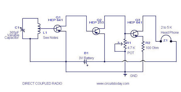
Direct Coupled Radio Circuit with Diagram
A simple direct-coupled radio circuit diagram and schematic, ideal for adjacent stations. This circuit uses Q1 as an audio amplifier, and the base-emitter capacitance provides radio filtering.
The described circuit is a direct-coupled radio receiver designed to effectively operate with nearby...
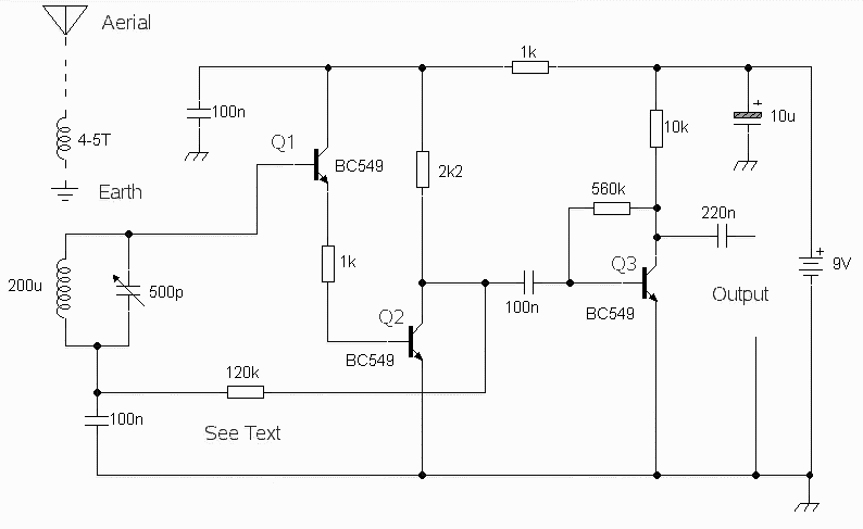
Amplitude Modulation Receiver Circuit
The circuit was designed to obtain signals through amplitude modulation, exhibiting good sensitivity and selectivity. Amplitude modulation.
The amplitude modulation (AM) circuit is engineered to effectively capture and process radio frequency signals. The design focuses on achieving high sensitivity, allowing for...
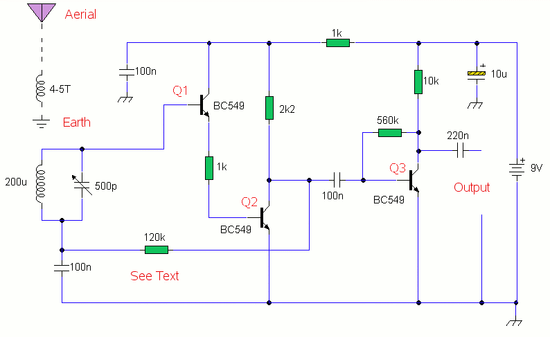
AM Receiver
This is a compact three-transistor regenerative receiver with fixed feedback. It operates similarly to the ZN414 radio IC, which has been replaced by the MK484. The design is straightforward, offering good sensitivity and selectivity. General-purpose transistors can be utilized in...
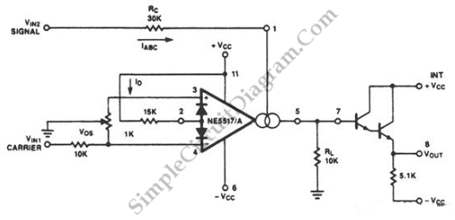
Amplitude Modulator with OTA
The circuit depicted in the schematic diagram below can achieve 99% modulation with a maximum frequency of 200 kHz. The amplification of this circuit can be...
This circuit is designed for high-efficiency amplitude modulation, capable of achieving a modulation depth of...
Wide Dynamic Range Field Strength Meter
A field strength meter is a useful tool for locating a transmitter. However, a sensitive field strength meter has limitations: it responds to nearly any RF signal entering its input. This characteristic reduces the effective sensitivity of the field strength...