


800 MHz Cellular Phone Jammer
#cellular jammer
#800 MHz
#RF oscillator
#Mini-Circuits ADE-1ASK
#impedance matching
#homebrew
#signal blocking
#wireless interference
#LO port
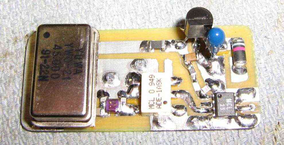
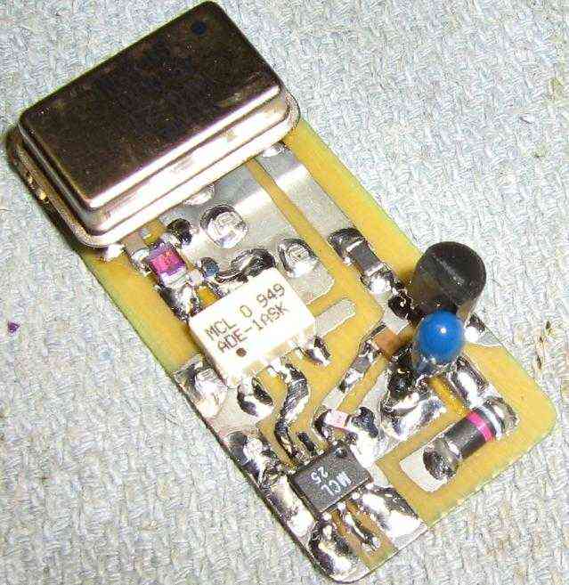
Description: This is a simple little 800 MHz band cellular phone jammer which can be easily built from commonly available parts. Most homebrew cellular phone jammers are based around a sweeping RF oscillator which, while more "jamming" efficient, can be quite difficult for the beginner to construct without access to expensive RF test equipment. This project can also be used to help take the load off certain people who receive 15 million emails a day from strangers asking them how to build their own cellular phone jammers. This cellular jammer is based around a common 45 MHz clock oscillator driving the Local Oscillator (LO) port on a Mini-Circuits ADE-1ASK mixer. This LO signal also passes through a simple impedance matching network to transform the high impedance of the clock oscillator down to the mixer port's 50 ohm impedance. The mixer's RF port (RF input) is connected directly to a 800 MHz band cellular phone antenna, and the IF port (RF output) is sent to a Mini-Circuits VNA-25 MMIC amplifier which increases the output jamming power by around 16 dB. This is then sent onto another 800 MHz band cellular phone antenna.
Here's the theory of operation... Any cellular phone that attempts to call out is immediately "jammed" by its own signal! This works because every 800 MHz band cellular phone's transmit and receive frequency are always separated by exactly 45 MHz.
Example: Say your cellular phone is transmitting at 837 MHz and receiving at 882 MHz. If you were to mix the 837 MHz transmitted signal with a 45 MHz signal, the new mixer output frequency would be 882 MHz - and the phone would essentially be jamming itself by "hearing" its own signal. This appears to work quite well on most cellular phones and should also work on full-duplex Nextel transmissions. A 45 MHz clock oscillator with an impedance matching network on the output feeds the LO port on a Mini-Circuits ADE-1ASK mixer. The ADE-1ASK mixer is only designed to operate up to 600 MHz, but it works fine for this particular use.
The IF output of the mixer feeds a Mini-Circuits VNA-25 MMIC amplifier to boost the output RF power slightly. The VNA-25 amplifier doesn't need any external components, so it's perfect for this application. The current draw is kinda high, though.
A 78L05 voltage regulator supplies the necessary voltage to the oscillator and VNA-25 from a standard nine volt battery. These types of jammers are also useful for defeating cellular-based vehicle tracking systems which record your travels via GPS then "burst" out a phone call in the middle of the night. It should also be useful for defeating GM's OnStar system and maybe even cellular phone detonated IEDs.
The circuit design for the 800 MHz cellular phone jammer incorporates several key components that work together to disrupt cellular communications effectively. At the heart of the circuit, the 45 MHz clock oscillator generates a stable frequency that is crucial for the mixing process. The oscillator is connected to an impedance matching network, which ensures that the oscillator's output impedance is compatible with the mixer’s input requirements, thus maximizing power transfer and minimizing signal reflection.
The Mini-Circuits ADE-1ASK mixer serves as the core component for frequency mixing. Although it is rated for operation up to 600 MHz, it is utilized in this design for its ability to mix the 45 MHz signal with the 800 MHz cellular frequency effectively. The RF input of the mixer is connected to a dedicated 800 MHz antenna, which captures the cellular signals in the vicinity. The mixer then produces an intermediate frequency (IF) output that corresponds to the jamming frequency.
To enhance the output power of the jamming signal, the IF output from the mixer is fed into a Mini-Circuits VNA-25 MMIC amplifier. This amplifier is designed for RF applications and provides a gain of approximately 16 dB, significantly boosting the jamming signal before it is transmitted through a second 800 MHz antenna.
The power supply for the entire circuit is managed by a 78L05 voltage regulator, which converts the voltage from a standard nine-volt battery to the required levels for the oscillator and amplifier. The design is straightforward, leveraging commonly available components, making it accessible for hobbyists and engineers alike.
Overall, this circuit provides a practical solution for generating a jamming signal within the 800 MHz cellular band, utilizing a combination of frequency mixing and amplification to achieve effective signal disruption. It is important to note that the use of jamming devices may be illegal in many jurisdictions; thus, this information is provided for educational purposes only.This is a simple little 800 MHz band cellular phone jammer which can be easily built from commonly available parts. Most homebrew cellular phone jammers are based around a sweeping RF oscillator which, while more "jamming" efficient, can be quite difficult for the beginner to construct without access to expensive RF test equipment.
This project can also be used to help take the load off certain people who receive 15 million emails a day from strangers asking them how to build their own cellular phone jammers. This cellular jammer is based around a common 45 MHz clock oscillator driving the Local Oscillator (LO) port on a Mini-Circuits ADE-1ASK mixer.
This LO signal also passes through a simple impedance matching network to transform the high impedance of the clock oscillator down to the mixer port's 50 ohm impedance. The mixer's RF port (RF input) is connected directly to a 800 MHz band cellular phone antenna, and the IF port (RF output) is sent to a Mini-Circuits VNA-25 MMIC amplifier which increases the output jamming power by around 16 dB. This is then sent onto another 800 MHz band cellular phone antenna. Here's the theory of operation... Any cellular phone that attempts to call out is immediately "jammed" by its own signal! This works because every 800 MHz band cellular phone's transmit and receive frequency are always separated by exactly 45 MHz.
Example: Say your cellular phone is transmitting at 837 MHz and receiving at 882 MHz. If you were to mix the 837 MHz transmitted signal with a 45 MHz signal, the new mixer output frequency would be 882 MHz - and the phone would essentially be jamming itself by "hearing" its own signal. This appears to work quite well on most cellular phones and should also work on full-duplex Nextel transmissions.
A 45 MHz clock oscillator with an impedance matching network on the output feeds the LO port on a Mini-Circuits ADE-1ASK mixer. The ADE-1ASK mixer is only designed to operate up to 600 MHz, but it works fine for this particular use.
The IF output of the mixer feeds a Mini-Circuits VNA-25 MMIC amplifier to boost the output RF power slightly. The VNA-25 amplifier doesn't need any external components, so it's perfect for this application. The current draw is kinda high, though. A 78L05 voltage regulator supplies the necessary voltage to the oscillator and VNA-25 from a standard nine volt battery.
These types of jammers are also useful for defeating cellular-based vehicle tracking systems which record your travels via GPS then "burst" out a phone call in the middle of the night. It should also be useful for defeating GM's OnStar system and maybe even cellular phone detonated IEDs.
Here's the theory of operation... Any cellular phone that attempts to call out is immediately "jammed" by its own signal! This works because every 800 MHz band cellular phone's transmit and receive frequency are always separated by exactly 45 MHz.
Example: Say your cellular phone is transmitting at 837 MHz and receiving at 882 MHz. If you were to mix the 837 MHz transmitted signal with a 45 MHz signal, the new mixer output frequency would be 882 MHz - and the phone would essentially be jamming itself by "hearing" its own signal. This appears to work quite well on most cellular phones and should also work on full-duplex Nextel transmissions. A 45 MHz clock oscillator with an impedance matching network on the output feeds the LO port on a Mini-Circuits ADE-1ASK mixer. The ADE-1ASK mixer is only designed to operate up to 600 MHz, but it works fine for this particular use.
The IF output of the mixer feeds a Mini-Circuits VNA-25 MMIC amplifier to boost the output RF power slightly. The VNA-25 amplifier doesn't need any external components, so it's perfect for this application. The current draw is kinda high, though.
A 78L05 voltage regulator supplies the necessary voltage to the oscillator and VNA-25 from a standard nine volt battery. These types of jammers are also useful for defeating cellular-based vehicle tracking systems which record your travels via GPS then "burst" out a phone call in the middle of the night. It should also be useful for defeating GM's OnStar system and maybe even cellular phone detonated IEDs.
The circuit design for the 800 MHz cellular phone jammer incorporates several key components that work together to disrupt cellular communications effectively. At the heart of the circuit, the 45 MHz clock oscillator generates a stable frequency that is crucial for the mixing process. The oscillator is connected to an impedance matching network, which ensures that the oscillator's output impedance is compatible with the mixer’s input requirements, thus maximizing power transfer and minimizing signal reflection.
The Mini-Circuits ADE-1ASK mixer serves as the core component for frequency mixing. Although it is rated for operation up to 600 MHz, it is utilized in this design for its ability to mix the 45 MHz signal with the 800 MHz cellular frequency effectively. The RF input of the mixer is connected to a dedicated 800 MHz antenna, which captures the cellular signals in the vicinity. The mixer then produces an intermediate frequency (IF) output that corresponds to the jamming frequency.
To enhance the output power of the jamming signal, the IF output from the mixer is fed into a Mini-Circuits VNA-25 MMIC amplifier. This amplifier is designed for RF applications and provides a gain of approximately 16 dB, significantly boosting the jamming signal before it is transmitted through a second 800 MHz antenna.
The power supply for the entire circuit is managed by a 78L05 voltage regulator, which converts the voltage from a standard nine-volt battery to the required levels for the oscillator and amplifier. The design is straightforward, leveraging commonly available components, making it accessible for hobbyists and engineers alike.
Overall, this circuit provides a practical solution for generating a jamming signal within the 800 MHz cellular band, utilizing a combination of frequency mixing and amplification to achieve effective signal disruption. It is important to note that the use of jamming devices may be illegal in many jurisdictions; thus, this information is provided for educational purposes only.This is a simple little 800 MHz band cellular phone jammer which can be easily built from commonly available parts. Most homebrew cellular phone jammers are based around a sweeping RF oscillator which, while more "jamming" efficient, can be quite difficult for the beginner to construct without access to expensive RF test equipment.
This project can also be used to help take the load off certain people who receive 15 million emails a day from strangers asking them how to build their own cellular phone jammers. This cellular jammer is based around a common 45 MHz clock oscillator driving the Local Oscillator (LO) port on a Mini-Circuits ADE-1ASK mixer.
This LO signal also passes through a simple impedance matching network to transform the high impedance of the clock oscillator down to the mixer port's 50 ohm impedance. The mixer's RF port (RF input) is connected directly to a 800 MHz band cellular phone antenna, and the IF port (RF output) is sent to a Mini-Circuits VNA-25 MMIC amplifier which increases the output jamming power by around 16 dB. This is then sent onto another 800 MHz band cellular phone antenna. Here's the theory of operation... Any cellular phone that attempts to call out is immediately "jammed" by its own signal! This works because every 800 MHz band cellular phone's transmit and receive frequency are always separated by exactly 45 MHz.
Example: Say your cellular phone is transmitting at 837 MHz and receiving at 882 MHz. If you were to mix the 837 MHz transmitted signal with a 45 MHz signal, the new mixer output frequency would be 882 MHz - and the phone would essentially be jamming itself by "hearing" its own signal. This appears to work quite well on most cellular phones and should also work on full-duplex Nextel transmissions.
A 45 MHz clock oscillator with an impedance matching network on the output feeds the LO port on a Mini-Circuits ADE-1ASK mixer. The ADE-1ASK mixer is only designed to operate up to 600 MHz, but it works fine for this particular use.
The IF output of the mixer feeds a Mini-Circuits VNA-25 MMIC amplifier to boost the output RF power slightly. The VNA-25 amplifier doesn't need any external components, so it's perfect for this application. The current draw is kinda high, though. A 78L05 voltage regulator supplies the necessary voltage to the oscillator and VNA-25 from a standard nine volt battery.
These types of jammers are also useful for defeating cellular-based vehicle tracking systems which record your travels via GPS then "burst" out a phone call in the middle of the night. It should also be useful for defeating GM's OnStar system and maybe even cellular phone detonated IEDs.
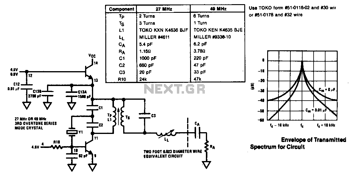
27Mhz and 49Mhz rf oscillator-transmitter
The modulator and oscillator comprise two NPN transistors. The base of the modulator transistor is powered by a bidirectional current source, with the voltage range for the high condition restricted by a saturating PNP collector connected to the pin 4...
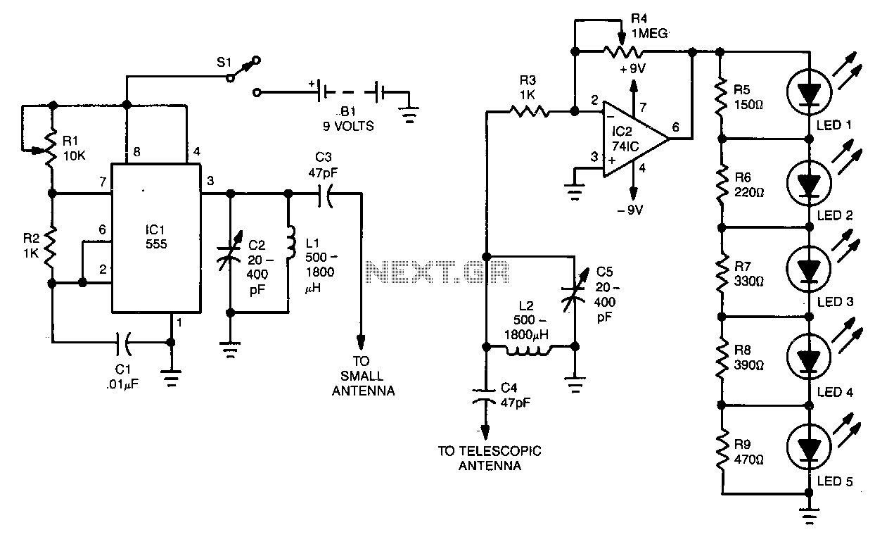
Automobile-locater
This locator consists of two main components. The first component is an RF oscillator, with its circuit illustrated in Fig. 8-4a. The second component is a sensitive receiver, depicted in Fig. 8-4b. The core of the oscillator is a 555...
Single Span HF Test Oscillator
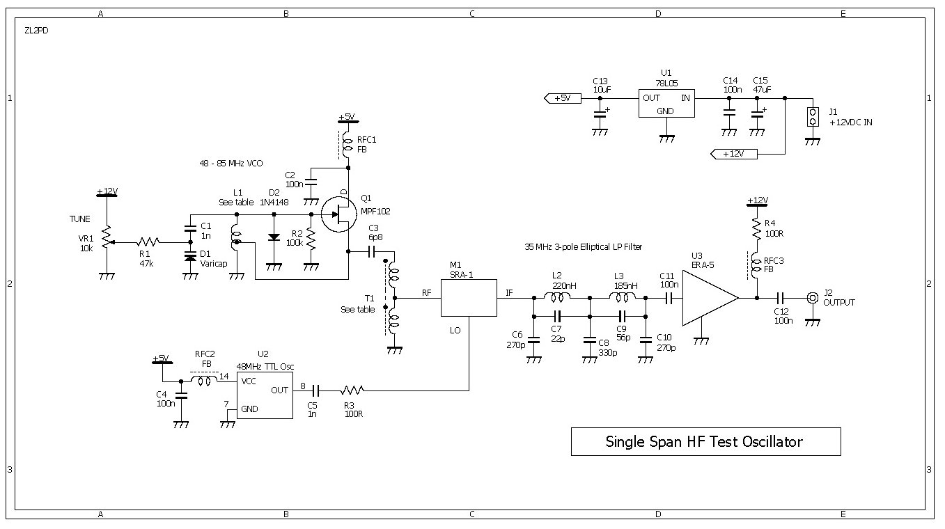
This compact RF oscillator operates across the entire frequency range of 0.4 to 30 MHz in a single sweep of the dial, featuring a terminated 50-ohm output of more than 300 mV throughout the HF band. Unlike most signal generators...
homebrew rf circuit design
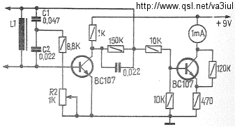
This time, we will share information about Yo3dac's homebrew RF circuit design ideas, including the latest updates from Onmilwiki.
Yo3dac is known for innovative approaches in the realm of radio frequency (RF) circuit design, particularly within the homebrew community. The RF...
Basic RF Oscillator
The signal can be received using a standard FM radio receiver. It should be coupled by a disc capacitor of approximately 0.1 µF to the main stage.
To implement a circuit capable of receiving the specified FM signal, a standard FM...
Metal Detectors
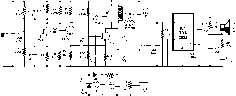
The circuit presented is a metal detector that operates based on the superheterodyne principle, which is commonly utilized in superhet receivers. It employs two RF oscillators, both fixed at a frequency of 5.5 MHz. The first RF oscillator consists of...
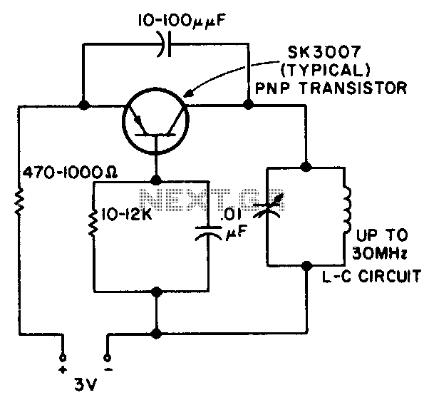
Rf oscillator
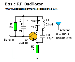
This RF oscillator is effective up to 30 MHz. An SK 3007 PNP transistor is recommended.
The described RF oscillator circuit operates within a frequency range of up to 30 MHz, making it suitable for various applications in radio frequency transmission...
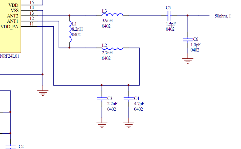
rf Can I merge two impedance matching circuits
Place the transceiver and the chip antenna very close together, eliminating the need for a 50-ohm transmission line. If this is the case, can the two matching circuits be merged into one to reduce the component count?
To create an efficient...
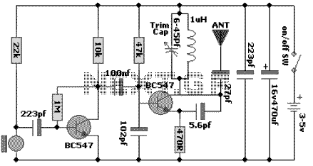
100 MHz RF Oscillator Circuit
The following schematic diagram shows the design of a 100 MHz Radio Frequency RF Oscillator Circuit. The electrets microphone picks up and amplifies sound then fed it into the audio amplifier stage built around the first transistor. The output from...