


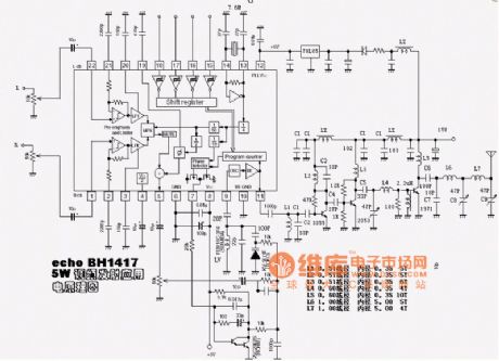
877 ~ 924MHz RF2152 power amplifier the circuit diagram
#RF2152
#power amplifier
#877MHz
#924MHz
#RF circuit
#high frequency
#wireless communication
#signal boosting
#transmitter
#RF design
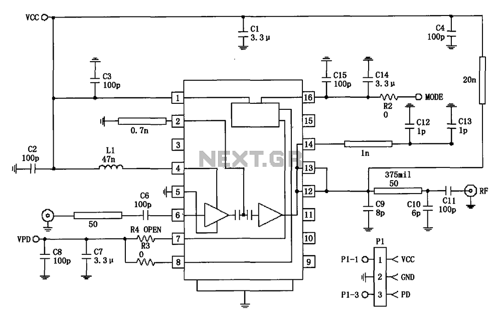
Description: 877 ~ 924MHz RF2152 power amplifier circuit diagram.
The RF2152 is a high-performance power amplifier designed for applications in the 877 to 924 MHz frequency range. This amplifier is typically used in various RF communication systems, including wireless networks and mobile communication devices.
The circuit diagram of the RF2152 power amplifier includes several key components to ensure efficient operation and signal integrity. The amplifier is typically powered by a suitable DC voltage source, which is connected to the Vcc pin. The device is designed to provide a significant gain while maintaining linearity, which is crucial for minimizing distortion in the transmitted signal.
Input matching networks are often employed at the input stage to optimize the impedance seen by the RF signal source, enhancing the power transfer to the amplifier. These matching networks may consist of inductors and capacitors configured to resonate at the desired frequency.
The output stage of the RF2152 includes a load matching network to ensure that the output impedance is compatible with the subsequent stage or antenna. This network is designed to maximize power transfer and minimize reflections, which can degrade performance.
Thermal management is also a critical aspect of the design, as power amplifiers generate heat during operation. Heat sinks or thermal pads may be utilized to dissipate heat effectively, ensuring the device operates within its specified temperature range.
Overall, the RF2152 power amplifier circuit is designed to provide robust performance in the specified frequency range, with careful consideration given to input and output matching, thermal management, and linearity to ensure high-quality signal amplification.877 ~ 924MHz RF2152 power amplifier constituting the circuit diagram:
The RF2152 is a high-performance power amplifier designed for applications in the 877 to 924 MHz frequency range. This amplifier is typically used in various RF communication systems, including wireless networks and mobile communication devices.
The circuit diagram of the RF2152 power amplifier includes several key components to ensure efficient operation and signal integrity. The amplifier is typically powered by a suitable DC voltage source, which is connected to the Vcc pin. The device is designed to provide a significant gain while maintaining linearity, which is crucial for minimizing distortion in the transmitted signal.
Input matching networks are often employed at the input stage to optimize the impedance seen by the RF signal source, enhancing the power transfer to the amplifier. These matching networks may consist of inductors and capacitors configured to resonate at the desired frequency.
The output stage of the RF2152 includes a load matching network to ensure that the output impedance is compatible with the subsequent stage or antenna. This network is designed to maximize power transfer and minimize reflections, which can degrade performance.
Thermal management is also a critical aspect of the design, as power amplifiers generate heat during operation. Heat sinks or thermal pads may be utilized to dissipate heat effectively, ensuring the device operates within its specified temperature range.
Overall, the RF2152 power amplifier circuit is designed to provide robust performance in the specified frequency range, with careful consideration given to input and output matching, thermal management, and linearity to ensure high-quality signal amplification.877 ~ 924MHz RF2152 power amplifier constituting the circuit diagram:
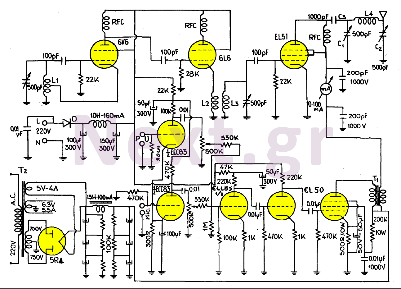
Valve Transmitter circuit 70W
This transmitter, equipped with a quality antenna and utilized under optimal conditions, can achieve a range exceeding 45 km. The configuration benefits from the output lamp's elevation, enhancing the fidelity of the transmitted signal. The 6V6 lamp is employed in...
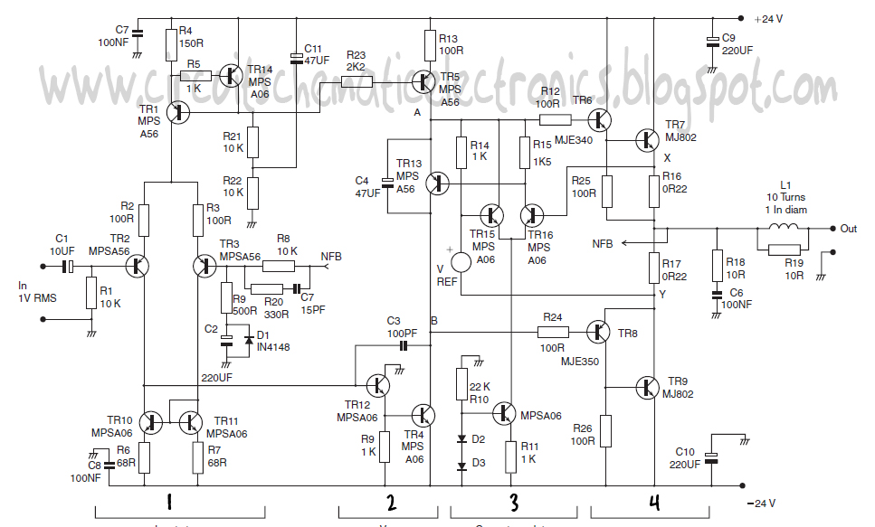
power amplifier class circuit
This design schematic represents a Class A power amplifier. It closely matches the operating parameters of Class B to facilitate comparison, particularly with a negative feedback (NFB) factor of 30dB at 20 kHz. The front end is similar to that...
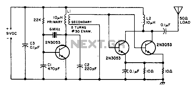
1W-cwtransmitter
This is a small transmitter designed to fit inside a plastic Easter egg. It delivers approximately 1 W of measured RF output into a 50-ohm dummy load and does not generate any heating issues within the circuit. The crystal used...
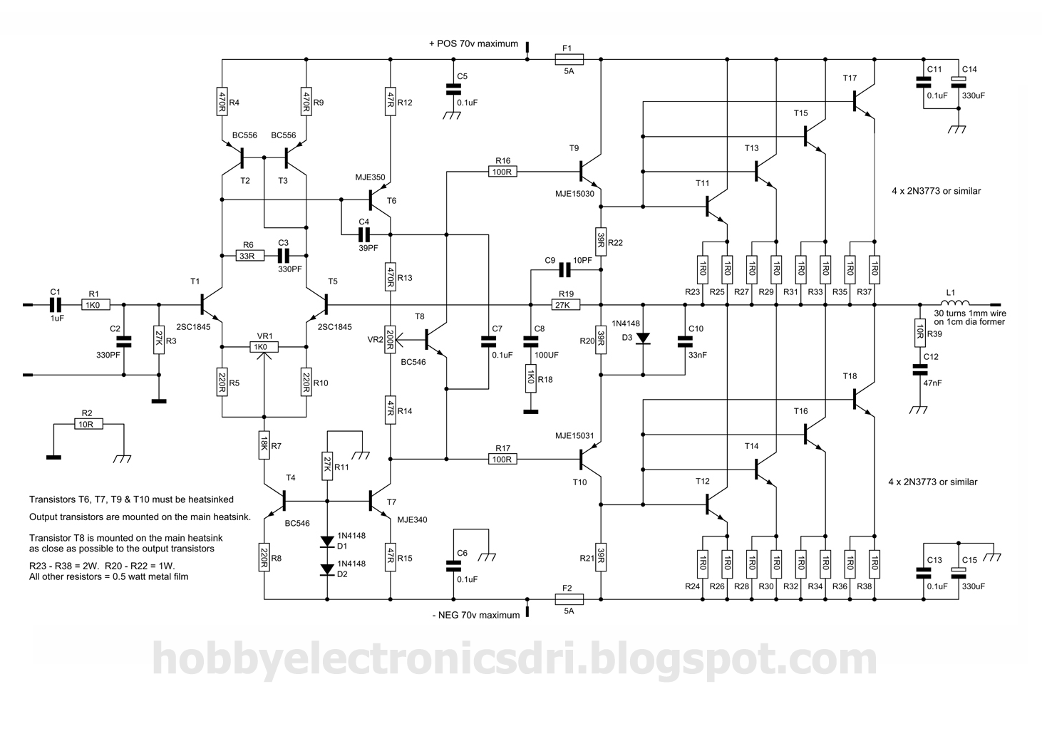
300w power amplifier circuit with 2n773
This amplifier was designed to utilize the otherwise unused TO3 power transistors that many hobbyists possess. With proper construction, the module can achieve high-quality performance and is rated for 300 watts into a 4-ohm load, depending on the power supply....
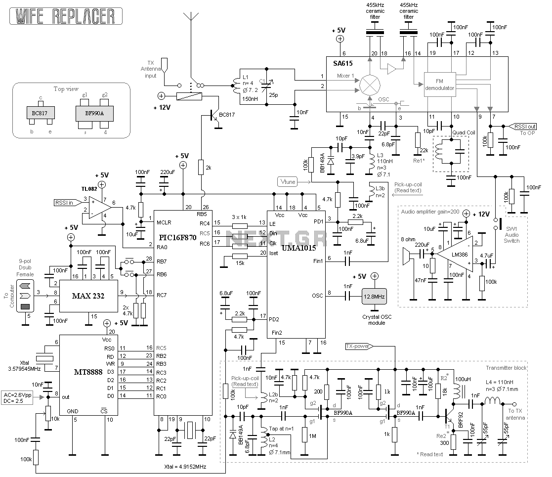
Remote tuning transmitter
This project consists of a wide range receiver and one transmitter. Together they will form a unit which will help you tuning your homebrewed transmitter. The most difficult part of homebrewing is the tuning part of the transmitters. How should...
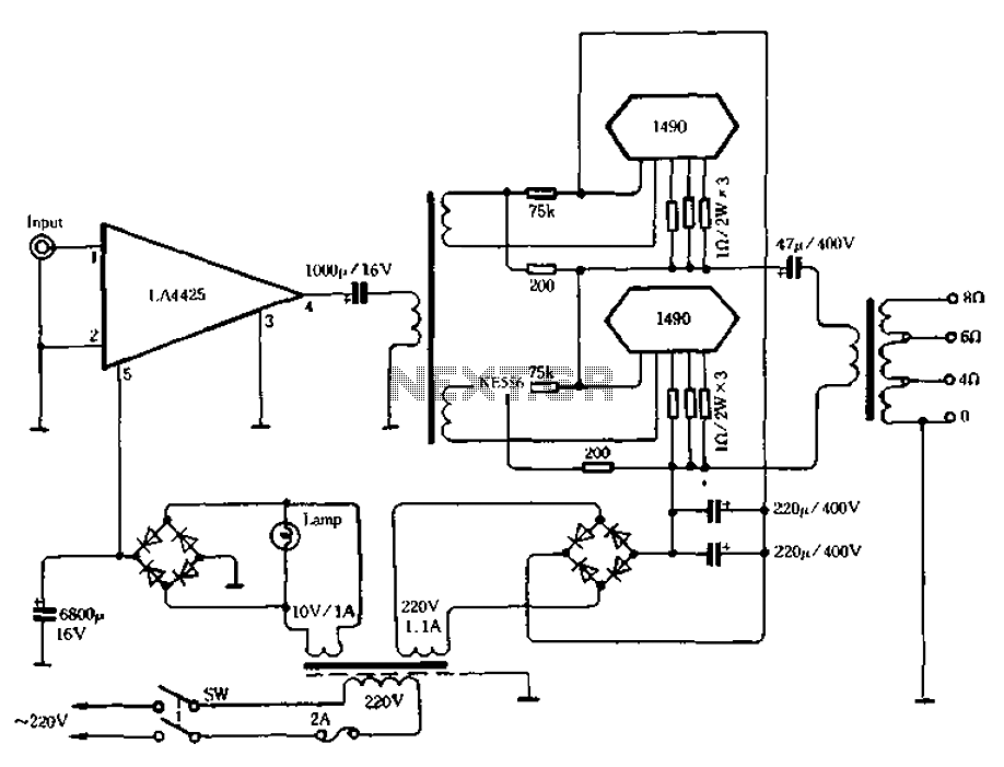
100W + 100W power amplifier
As illustrated in Figure 3-30, the IC LA4425 power amplifier stage is utilized alongside a pair of power module 1490 configured for push-pull output. This setup functions as an impedance converter, enabling the system to deliver 100 watts of output...
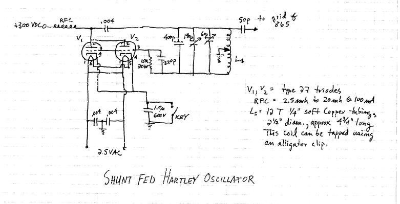
1929 MOPA 80 meter transmitter using a pair of 27 triodes to an 865 tetrode
This transmitter originated as a conventional shunt-fed Hartley oscillator for 80 meters, utilizing a pair of 27 triodes connected in parallel. With 300 VDC applied to the plates of the 27s, it produced approximately 4 watts of output with decent...
Wireless Transmitter
A basic circuit of the transistor UHF radio transmitter with a surface acoustic wave resonator (SAW) is presented. The SAW is utilized as a positive feedback element connected between the transistor's base and an LC network in parallel. In this...
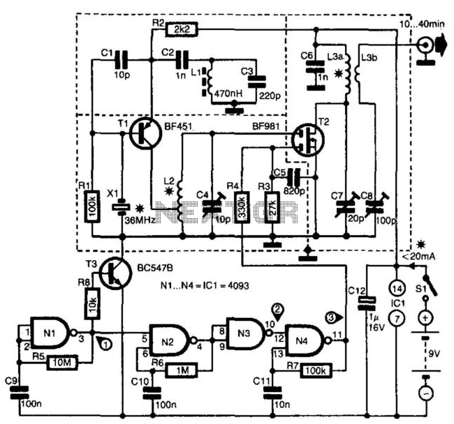
2M Transmitter
The transmitter is specifically designed for radio amateurs to function as a radio beacon, delivering a high-quality signal devoid of unwanted harmonics. Transistor T1, in conjunction with crystal X1, serves as a 36-MHz oscillator. Filter L1/C3 prevents the circuit from...